Table of Contents
Advertisement
Available languages
Available languages
OPERATOR'S MANUAL
MANUEL D'UTILISATION
MANUAL DEL OPERADOR
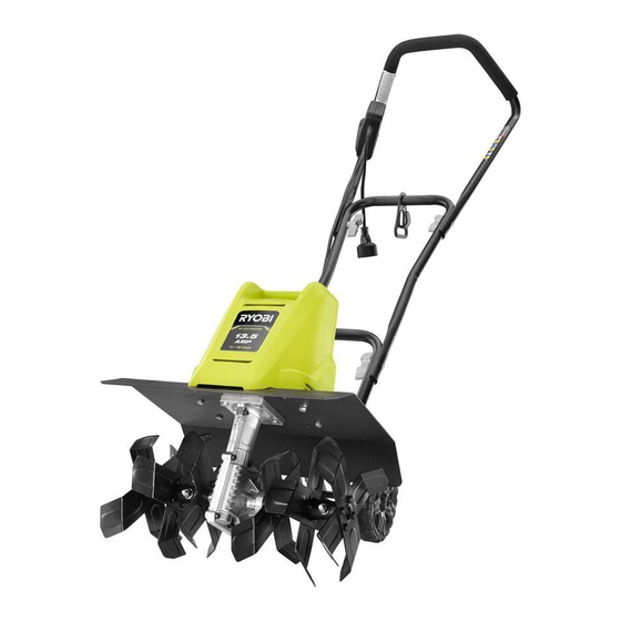
ELECTRIC CULTIVATOR
CULTIVATEUR ÉLECTRIQUE
CULTIVADORA ELÉCTRICA
RYAC701
TABLE OF CONTENTS
Important Safety Instructions .......... 2-4
Symbols ..............................................5
Electrical .............................................6
Features ..............................................7
Assembly ........................................ 7-9
Operation ...................................... 9-11
Maintenance .....................................11
Troubleshooting ................................12
Parts Ordering/Service ........ Back Page
WARNING:
To reduce the
risk of injury, the user must read and
understand the operator's manual
before using this product.
SAVE THIS MANUAL FOR
FUTURE REFERENCE
TABLE DES MATIÈRES
concernant la sécurité..................... 2-4
Symboles ............................................5
Caractéristiques électriques ...............6
Caractéristiques ..................................7
Assemblage .................................... 7-9
Utilisation ...................................... 9-11
Entretien ............................................11
Dépannage ........................................12
Commande de pièces/
réparation .......................... Páge arrière
AVERTISSEMENT :
réduire les risques de blessures,
l'utilisateur doit lire et veiller à bien
comprendre le manuel d'utilisation
avant d'employer ce produit.
CONSERVER CE MANUEL
POUR FUTURE RÉFÉRENCE
ÍNDICE DE CONTENIDO
Instrucciones de seguridad
importantes ..................................... 2-4
Símbolos .............................................5
Aspectos eléctricos ............................6
Características ....................................7
Armado ........................................... 7-9
Funcionamiento ............................ 9-11
Mantenimiento ..................................11
Correción de problemas ...................12
Pedidos de piezas/
servicio ........................... Pág. posterior
Pour
ADVERTENCIA:
el riesgo de lesiones, el usuario debe
leer y comprender el manual del
operador antes de usar este producto.
GUARDE ESTE MANUAL
PARA FUTURAS CONSULTAS
Para reducir
Advertisement
Table of Contents

Related Manuals for Ryobi RYAC701


Summary of Contents for Ryobi RYAC701
-
Page 1: Table Of Contents
OPERATOR’S MANUAL MANUEL D’UTILISATION MANUAL DEL OPERADOR ELECTRIC CULTIVATOR CULTIVATEUR ÉLECTRIQUE CULTIVADORA ELÉCTRICA RYAC701 TABLE OF CONTENTS TABLE DES MATIÈRES ÍNDICE DE CONTENIDO Instructions importantes Instrucciones de seguridad Important Safety Instructions ..2-4 concernant la sécurité..... 2-4 importantes ........ - Page 2 See this fold-out section for all of the figures referenced in the operator’s manual. Consulter l’encart à volets afin d’examiner toutes les figures mentionnées dans le manuel d’utilisation. Consulte esta sección desplegable para ver todas las figuras a las que se hace referencia en el manual del operador.
- Page 3 Fig. 1 A - Cord retainer (retenue de cordon, retén para el cordón) G - Tines (dents, púas) B - Lock-out button (bouton de verrouillage, botón de seguro) H - Plug connector (fiche connecteur, conector de la clavija) C - Switch trigger (gâchette, gatillo del interruptor) I - Tine shield (arbre de lames, protector de las aspas) D - Upper handle (poignée supérieure, mango superior) J - Lock pin (goupille de verrouillage, pasador de fijación)
- Page 4 Fig. 2 Fig. 4 A - Knob (bouton, perilla) B - Lower handle (poignée inférieure, mango inferior) C - Bolt (boulon, perno) D - Groove (rainure, ranura) E - Bar (barre, barra) Fig. 3 A - Upper handle (poignée supérieure, mango superior) B - Lower handle (poignée inférieure, mango inferior) C - Switch trigger cable (câble decommutateur, cable del interruptor) Fig.
- Page 5 Fig. 6 VIEW FROM THE FRONT Fig. 9 VIEW FROM THE FRONT (VUE DE FACE, VISTA DESDE EL FRENTE) (VUE DE FACE, VISTA DESDE EL FRENTE) A - Inner tine assembly A (assemblages de dents intérieurs « A », conjuntos de púas internas “A”) B - Tine shaft (arbre de dents, eje de las púas) A - Lock pin (goupille de verrouillage, pasador de fijación) C - Lock pin (goupille de verrouillage, pasador de fijación)
- Page 6 Fig. 14 Fig. 12 POSITION "B" POSITION «B» / POSICIÓN “B” A - Wheel assembly (ensemble de roues, conjunto de rueda) B - Bracket (support, soporte) C - Notch (encoche, muesca) D - Tab (ergot, orejeta) Fig. 15 Fig. 13 POSITION "C"...
- Page 7 Fig. 16 Fig. 17 REGULAR TINE PATTERN / DISPOSITION NORMALE DES LAMES DENTÉES / PATRÓN DE ASPAS REGULAR A - Inner tine assembly A (assemblages de dents intérieurs « A », conjuntos de púas internas “A”) B - Outer tine B (dent extérieure B, púa exterior B) C - Outer tine C (dent extérieure C, púa exterior C) Fig.
-
Page 8: Important Safety Instructions
IMPORTANT SAFETY INSTRUCTIONS Make sure your extension cord is in good condition. When using an extension cord, be sure to use one heavy WARNING: enough to carry the current your product will draw. A wire READ AND UNDERSTAND ALL INSTRUCTIONS. gauge size (A.W.G.) of at least 14 is recommended for an Failure to follow all instructions listed below and on the extension cord 50 feet or less in length. - Page 9 IMPORTANT SAFETY INSTRUCTIONS Stay alert, watch what you are doing and use common Store Idle Cultivators Indoors — When not in use, sense when operating a power cultivator. Do not use cultivator should be stored indoors in a dry, locked up cultivator while tired, upset, ill, or under the influence of place —...
- Page 10 IMPORTANT SAFETY INSTRUCTIONS If the cultivator strikes a foreign object, follow these steps: Check Damaged Parts - Before further use of the appliance, a guard or other part that is damaged should • Release the switch trigger and wait until the unit comes be carefully checked to determine that it will operate to a complete stop.
-
Page 11: Symbols
SYMBOLS The following signal words and meanings are intended to explain the levels of risk associated with this product. SYMBOL SIGNAL MEANING Indicates a hazardous situation, which, if not avoided, will result in death or DANGER: serious injury. Indicates a hazardous situation, which, if not avoided, could result in death or WARNING: serious injury. -
Page 12: Electrical
ELECTRICAL DOUBLE INSULATION EXTENSION CORDS Double insulation is a concept in safety in electric power When using a power tool at a considerable distance from tools, which eliminates the need for the usual three- a power source, be sure to use an extension cord that has wire grounded power cord. -
Page 13: Features
FEATURES PRODUCT SPECIFICATIONS Input ........................nominal 120V/60Hz AC only, 13.5 Amps Number of Tines ..................................6 Cultivating Depth ................................8 in. Cultivating Width ................................16 in. KNOW YOUR CULTIVATOR LOCK-OUT BUTTON See Figure 1. The lock-out button prevents accidental starting of the cultivator. - Page 14 ASSEMBLY INSTALLING THE HANDLE ASSEMBLY INSTALLING THE TINES See Figures 2 - 3. See Figures 6 - 10. Place the lower handle onto the bar on the cultivator. The inner tine assemblies are marked “A”. The right outer tine is marked “C” and the left outer tine is marked “B”. For NOTE: The bar should fit inside the grooves in the lower correct operation of the unit, the tines must be installed in handle.
-
Page 15: Operation
ASSEMBLY CHANGING WHEEL POSITIONS NOTE: The spring loaded wheel assembly will snap forward if released. See Figures 12 - 15. Slowly bring the wheel assembly toward the bracket and The wheel position of the unit is adjustable. Adjust the seat the tabs on the wheel assembly into a set of notches position of the wheels by placing the tabs on the wheel on the bracket. - Page 16 OPERATION Place your thumb on the lock-out button. Adjust the position of the wheel assembly for shallow, moderate, or deep cultivation (refer to Changing Wheel Pull the switch trigger toward the handle. Positions). Release the lock-out button. NOTE: Based on the type of soil being cultivated and To stop the motor: soil conditions at the time, the appropriate position of...
-
Page 17: Maintenance
OPERATION To change to a narrow tine pattern: Remove the outer tines. Remove the lock pins securing the outer tines from each When work is complete, place the outer tine marked “C” side of the cultivator. on the right side of the tine shaft and the outer tine marked “B”... -
Page 18: Troubleshooting
Your product has been fully tested prior to shipment to ensure your complete satisfaction. For any questions about operating or maintaining your product, call the RYOBI Help Line! This product has a Five-year Limited Warranty for personal, family, or household use (90 days for business or commercial use). -
Page 19: Instructions Importantes Concernant La Sécurité
INSTRUCTIONS IMPORTANTES CONCERNANT LA SÉCURITÉ Assurez-vous que le cordon d’extension est en bon état. Quand vous utilisez le cordon d’extension, assurez-vous AVERTISSEMENT: d’utiliser un cordon de calibre approprié pour rapporter LISEZ ET VEILLEZ À COMPRENDRE TOUTES LES le courant que votre produit soutirera. Pour un cordon INSTRUCTIONS. - Page 20 INSTRUCTIONS IMPORTANTES CONCERNANT LA SÉCURITÉ Entreposer les cultivateurs à l’intérieur — Lorsqu’il n’est pas Rester attentif, prêter attention au travail et faire preuve de bon sens lors de l’utilisation de tout cultivateur motorisé. utilisé, les cultivateurs doit être rangé à l’intérieur dans un Ne pas utiliser cet cultivateur en état de fatigue, vexé, de endroit sec et sous verrou, débranché...
- Page 21 INSTRUCTIONS IMPORTANTES CONCERNANT LA SÉCURITÉ Ne pas surcharger la machine en essayant de travailler à bon état de fonctionnement et de performance pour lequel une profondeur ou une vitesse excessives. il a été conçu. S’assurer du bon alignement des pièces mobiles, que les pièces mobiles sont perpendiculaires et ...
-
Page 22: Symboles
SYMBOLES Les termes de mise en garde suivants et leur signification ont pour but d’expliquer le degré de risques associé à l’utilisation de ce produit. SYMBOLE SIGNAL SIGNIFICATION Indique une situation dangereuse qui, si elle n’est pas évitée, aura pour DANGER : conséquences des blessures graves ou mortelles. -
Page 23: Caractéristiques Électriques
CARACTÉRISTIQUES ÉLECTRIQUES DOUBLE ISOLATION CORDONS PROLONGATEURS La double isolation est un dispositif de sécurité utilisé sur les Lors de l’utilisation d’un outil électrique à grande distance outils à moteur électriques, éliminant le besoin de cordon d’une prise secteur, veiller à utiliser un cordon prolongateur d’alimentation habituel à... -
Page 24: Caractéristiques
CARACTÉRISTIQUES FICHE TECHNIQUE Alimentation................caractéristique nominal CA de 120V/60 Hz seulement, 13,5 A Nombre de dents................................... 6 Profondeur de labourage ............................. 203,2 (8 po) Largeur de labourage ............................406,4 (16 po) APPRENDRE À CONNAÎTRE LE CULTIVATEUR BOUTON DE VERROUILLAGE Voir la figure 1. Le bouton de verrouillage prévient les démarrages accidentels. - Page 25 ASSEMBLAGE INSTALLATION DE L’ASSEMBLAGE DES INSTALLATION DES DENTS POIGNÉES Voir les figures 6 à 10. Voir les figures 2 et 3. Les assemblages de dents intérieurs sont marqués par un « A ». La dent extérieure droite est marquée par un « C » et ...
-
Page 26: Utilisation
ASSEMBLAGE CHANGEMENT DE POSITION DES ROUES NOTE : L’assemblage des roues à ressorts claquera en avant s’il est relâché. Voir les figures 12 à 15. Approcher lentement l’assemblage des roues vers le La position des roues de l’appareil peut être ajustée. support et positionner les languettes de l’assemblage Régler la position des roues en plaçant les languettes de dans un groupe d’encoches du support. - Page 27 UTILISATION MISE EN MARCHE / ARRÊT DU CULTIVATEUR Le cultivateur peut servir à briser la terre et à préparer un lit de semence. Prévoir de laisser assez de place entre les Voir la figure 17. rangées de semence pour pouvoir utiliser le cultivateur une Pour faire démarrer le moteur : fois les plantes poussées.
-
Page 28: Entretien
UTILISATION NOTE: La dent extérieure droite est marquée par un « C » NOTE : Ne pas forcer pour mettre les lames dentées sur et la dent extérieure gauche par un « B ». l’axe ou les retirer. En cas de difficultés pour retirer les lames dentées, appliquer une lubrifiant pénétrante sur l’arbre. -
Page 29: Dépannage
Pour toute question concernant l’utilisation ou l’entretien du produit, appeler le service d’assistance téléphonique RYOBI ! Ce produit est accompagné d’une garantie limitée de cinq (5) ans pour utilisation personnel, familiales ou domestiques (90 jours pour utilisation affaires ou commerciaux). - Page 30 INSTRUCCIONES DE SEGURIDAD IMPORTANTES Asegúrese de que esté en buen estado el cordón de extensión. Al utilizar un cordón de extensión, utilice uno del suficiente ADVERTENCIA: calibre para soportar la corriente que consume el producto. Se LEA Y COMPRENDA TODAS LAS INSTRUCCIONES. El recomienda que los conductores sean de calibre 14 (A.W.G.) incumplimiento de las instrucciones señaladas abajo y en la por lo menos, para un cordón de extensión de 15 m (50 pies)
- Page 31 INSTRUCCIONES DE SEGURIDAD IMPORTANTES Si el aparato de mano no está funcionando adecuadamente, Mantenga los pies bien afirmados y el equilibrio. No trate de se dejó caer, se daño, se dejó a la intemperie, o se dejó caer alcanzar demasiado lejos.
- Page 32 INSTRUCCIONES DE SEGURIDAD IMPORTANTES No sobrepase la capacidad de la máquina al intentar cultivadora Verifique la alineación de las partes móviles, que no haya con mucha profundidad o una velocidad muy rápida. atoramiento de partes móviles, que no haya piezas rotas, el montaje de las piezas y cualquier otra condición que pudiera ...
- Page 33 SÍMBOLOS Las siguientes palabras de señalización y sus significados tienen el objeto de explicar los niveles de riesgo relacionados con este producto. SÍMBOLO SEÑAL SIGNIFICADO Indica una situación peligrosa, la cual, si no se evita, causará la muerte o le- PELIGRO: siones serias.
- Page 34 ASPECTOS ELÉCTRICOS DOBLE AISLAMIENTO CORDONES DE EXTENSIÓN El doble aislamiento es una característica de seguridad de Al utilizar una herramienta eléctrica a una distancia las herramientas eléctricas, la cual elimina la necesidad considerable de la fuente de voltaje, asegúrese de utilizar de usar el típico cordón eléctrico de tres conductores con un cordón de extensión con la suficiente capacidad para conexión a tierra.
- Page 35 CARACTERÍSTICAS ESPECIFICACIONES DEL PRODUCTO Corriente de entrada ................capacidad de 120 V/60 Hz CA únicamente, 13,5 A Cantidad de púas .................................. 6 Profundidad de cultivo ............................. 203,2 (8 pulg.) Ancho de cultivo ............................. 406,4 (16 pulg.) FAMILIARÍCESE CON LA CULTIVADORA BOTÓN DE SEGURO Vea la figura 1.
- Page 36 ARMADO INSTALACIÓN DEL CONJUNTO DEL MANGO INSTALACIÓN DE LAS PÚAS Vea las figuras 2 y 3. Vea las figuras 6 a 10. Coloque el mango inferior sobre la barra de la cultivadora. Los conjuntos de púas interno están marcados con la letra “A”.
- Page 37 ARMADO CÓMO CAMBIAR LAS POSICIONES DE LAS NOTA: El conjunto de la rueda accionado mediante RUEDAS resorte se moverá hacia adelante si se suelta. Vea las figuras 12 a 15. Lentamente, lleve el conjunto de la rueda hacia el soporte y coloque las pestañas sobre el conjunto de la rueda en La posición de la rueda de la unidad puede regularse.
- Page 38 FUNCIONAMIENTO ENCENDIDO Y APAGADO DE LA CULTIVADORA La cultivadora puede utilizarse para mullir la tierra del jardín y preparar un lecho de tierra para plantar semillas. Planifique Vea la figura 17. para dejar suficiente espacio entre las hileras de semillas Para arrancar el motor: con el fin de permitir el cultivo con máquina una vez crecidas Conecte la cultivadora al suministro de corriente.
- Page 39 FUNCIONAMIENTO NOTA: No fuerce las púas para colocarlas o desprenderlas Retire las púas externas. del eje. Si surgen dificultades al retirar las púas, aplique al Cuando finalice el trabajo, la púa externa con la letra “C” eje un poco de aceite de baja viscosidad. Al volver a instalar se encontrará...
- Page 40 ¡Si tiene preguntas sobre el funcionamiento o el mantenimiento del producto, llame al teléfono de atención al consumidor de RYOBI! Este producto tiene una garantía limitada de cinco años para fines personales, familiares o domésticos (90 días para usos trabajo o comercial).
- Page 41 NOTES / NOTAS...
- Page 42 1-800-860-4050. RYOBI is a registered trademark of Ryobi Limited and is used pursuant to a license granted by Ryobi Limited. • PIÈCES ET SERVICE : Avant de faire la demande de service ou l’achat de pièces de remplacement, veuillez obtenir le numéro d’article, le numéro de fabrication et le numéro de série à...
Need help?
Do you have a question about the RYAC701 and is the answer not in the manual?
Questions and answers
Need instructions on how to replace the trigger on a Ryac701
To replace the trigger (Switch Push Rod) on a Ryobi RYAC701:
1. Unplug the unit from the power source.
2. Do not remove the motor cover.
3. Identify and access the switch push rod area, typically located near the upper handle where the switch trigger cable connects.
4. Carefully loosen and remove any fasteners or knobs securing the handle if needed to reach the part.
5. Remove the damaged switch push rod.
6. Install the new switch push rod (part number 996915001).
7. Reassemble all components securely.
8. Ensure the switch trigger cable is not pinched when lowering or adjusting the handle.
9. Plug in the unit and test the trigger function.
If unsure or if the part is difficult to access, contact an authorized service center.
This answer is automatically generated
@Mr. Anderson
Need to replace the Plastic Handel for the power lever
@Sandra Martin
Need to know source for Ryobi RYAC701 cultivator carbon brushes
Replacement parts for the Ryobi RYAC701 cultivator, including carbon brushes, can be purchased online at www.ryobitools.com or by calling 1-800-860-4050. They can also be obtained at a Ryobi service center.
This answer is automatically generated
need switch tigger replacement for roybi 701 electric tiller
You can replace the switch trigger for the Ryobi RYAC701 electric tiller by ordering the necessary part and following these steps:
1. Order the Replacement Part: The switch push rod (part number 996915001) is listed as available and usually ships within 7–12 business days. You can purchase it from an authorized parts supplier.
2. Disconnect Power: Ensure the tiller is unplugged from any power source for safety.
3. Access the Switch Mechanism: Do not remove the motor cover, but follow the instructions to carefully access the switch trigger area.
4. Remove the Broken Part: Detach the damaged switch trigger component carefully.
5. Install the New Switch Push Rod: Insert the replacement switch push rod and ensure it is securely in place.
6. Test the Tiller: After reassembly, plug in the tiller and test the switch trigger to confirm proper operation.
If you encounter issues, consider contacting an authorized service dealer for assistance.
This answer is automatically generated
Trigger lever broke, purchased one online. The parts inside came apart during removal of trigger lever. Need instructions on how assembly of trigger lever compartment goes