Advertisement
Quick Links
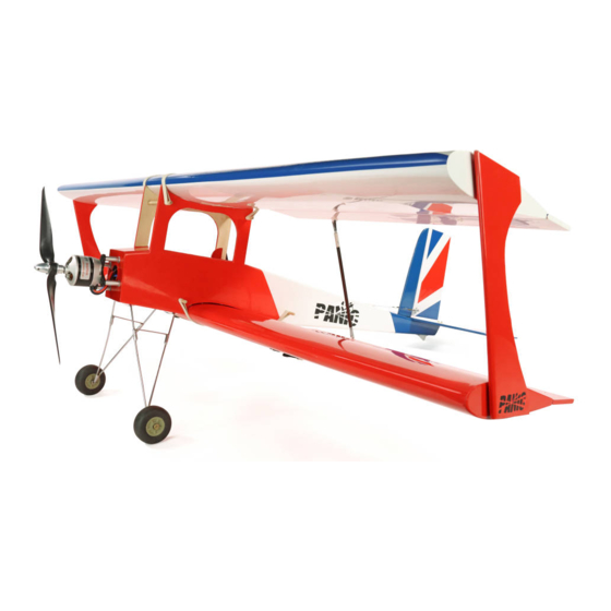
Introduction
It's hard to believe that the original Avicraft Panic was
designed over 39 years ago, yet it's as relevant now as it
was back in 1982 when creator, Phil Newman, took pen to
upturned wallpaper and began draughting. The result was a
superficially
simple
yet
sportster that could not only fly the book and take the
knocks but offered immense versatility from its eclectic
choice of engines. Fast forward four decades and the Panic
remains as entertaining as ever. Modified by the team at JP
to
meet
the
exacting
performance-savvy pilots, this new ARTF version of the
club favourite is not only light in weight and beautifully built,
it caters for both i.c. and electric power plants and anyone
with a thirst for 3D flight.
Recommended electric set-up
● EnErG 60 IC brushless motor (4445810).
● ZTW 80A brushless ESC (ZTW3080201). If used the
main power lead will need extending.
● APC 13X8 electric propeller (APCLPB13080E).
● Radient 4s 5000mAh 50C LiPo (RDNB50004S50H).
Recommended i.c. set-up
● Force 52 ABC two-stroke glow engine (FORE-5201).
Recommended servos
● Hitec HS5645MG (2217620) or HS5625MG (2217610).
Additional items required
Please note that glues, suitable radio control equipment,
servo extension leads and some good-quality tools will be
required to complete this model. Since the ARTF Panic is
not a beginner's aircraft, these additional items are left to
the discretion and experience of the builder.
Build tips
● Before commencing the build, use a covering iron with a
covering sock to carefully tighten any wrinkles that may
be evident as a result of temperature changes during
shipping.
● Always test / dry fit items before glueing.
● Ensure that no gaps are visible when attaching the
control surfaces.
● When fitting control horns always make sure the pin hole
for the clevis is positioned directly over the hinge line.
● Measure twice, cut once.
ingeniously cunning biplane
requirements
of
today's
● Most importantly, enjoy the build!
Box contents
Before you commence building, please check that you have
all the relevant pre-built parts and accessories listed below.
Pre-built and covered parts
1x Fuselage
2x Wing panels
1x Tailplane
1x Vertical fin
2x Interplane struts
Accessories
1x Engine mount
4x M4 x 20 bolts
4x M4 blind nuts
4x M4 x 25 bolts
4x M4 self-lock nuts
4x Washer for M4 screw
1x Throttle pushrod 2mm x 550mm
1x Nylon clevis
1x Swing keeper
23x Control surface hinges
3x Single control horns
1x Double control horn
1x Closed loop wire
2x 2mm Closed loop rod adjusters
2x 2mm nuts
2x 2mm metal clevises
4x Brass ferrules
2x 2mm aileron pushrods
2x 2mm metal clevises
2x Aileron pushrod swing keepers
2x 3mm aileron pushrods
4x 3mm metal clevises
4x 3mm nuts
4x Composite aileron link rod horns
8x Press stud sets for interplane struts
1x Undercarriage (prefabricated)
4x Undercarriage saddle clamps and screws
2x Wheels (2.5")
4x Wheel collets
1x Tail skid
1x Elevator pushrod (carbon)
2x 2mm pushrods
2x 2mm metal clevises
2x 2mm nuts
2x Closed loop tubes
4x Electric motor stand-offs
4x Motor stand-off washers
1x Fuel tank
4x Wing dowels
4x 3mm ply parts for EP set-up
Please read these instructions fully before
commencing your build
Advertisement

Subscribe to Our Youtube Channel
Related Manuals for J. Perkins Panic


Summary of Contents for J. Perkins Panic
- Page 1 2x Interplane struts Accessories Introduction 1x Engine mount It’s hard to believe that the original Avicraft Panic was 4x M4 x 20 bolts designed over 39 years ago, yet it’s as relevant now as it 4x M4 blind nuts was back in 1982 when creator, Phil Newman, took pen to 4x M4 x 25 bolts upturned wallpaper and began draughting.
- Page 2 Step 3 and 4. process again for all the other hinges. Allow to dry. DECISION TIME! Your Panic has been designed to cater ▢ 3. Starting with the top wing, insert the ailerons as shown.
- Page 3 ▢ 6. Positioned 115mm away from the inboard end of each ▢ 9. Identify the upper side of the bottom wing. This is aileron is a slot for the aileron link rod horn. Remove the evident by the two covered servo lead holes that are drilled film that covers this slot from the underside of the top wing in the centre-section of the panel.
- Page 4 ▢ 12. Using your chosen servo (Hitec HS5645MG ▢ 15. Once complete use a small cable tie to hold the two recommended), attach the servo lead to the drawstring and servo leads together. Cut away any excess bolt thread gently pull it through the wing and out through the hole on projecting through the nut on the aileron control horn the upper side.
- Page 5 WARNING! Take great care in the next step not to cut into ▢ 21. As a guide for permanently attaching the tailplane and the balsa when removing the film as this could seriously fin you’ll need to mount the bottom wing. To do this, locate compromise the structural integrity of the tailplane.
- Page 6 ▢ 24. Drill the holes and secure the captive nuts in the back ▢ 27. Glue together the parts for the battery and ESC tray, of the firewall. A top tip to facilitate this is to use a length of as shown.
- Page 7 ▢ 29. With the battery tray in place, positioned so that the ESC tray is located closest to the firewall, run some slow cure glue along the mating surfaces. This is best done by lifting one side up whilst the tray is in place, running the glue along the edge, then pushing the plate back down to locate on the pegs, before repeating the process on the other side of the tray.
- Page 8 ▢ 36. Having chosen to power your Panic with an IC engine, the battery hatch cover between the cabane struts should be permanently glued in place and reinforced with the supplied triangular stock balsa.
- Page 9 ▢ 38. Fit the fuel tank to the fuselage allowing the throttle cable to pass unrestricted beneath it. This can be facilitated using some packing sponge. ▢ 39. Cut a slot in the forward servo mounting tray to accommodate your chosen throttle servo, then install the WARNING! In order to facilitate numerous servo sizes the servo as shown.
- Page 10 ▢ 42. Using the supplied items shown in Step A below, ▢ D. Carefully slide the bent end of the piano wire section follow Steps A – D and make the elevator pushrod. At the inside the carbon tube and locate it in the 3mm hole. end of the process the pushrod should measure Slightly angling the bend on the end of the piano wire can approximately 610mm from the elevator servo clevis pin to...
- Page 11 ▢ 45. Using the pushrod to align the control horn on the ▢ 48. Remove the film that covers the two holes just forward elevator, mark the positions of the fixing holes whilst making of the servo tray in the rear of the fuselage. With the holes sure that the pushrod is clear of the fin post that sits in the exposed use a needle file to create a taper that allows the middle of the fuselage.
- Page 12 clevis adjusters to the rudder end and not the servo end as the male studs can be glued. Glue the studs in place with this will enable the elevator and rudder servo to operate epoxy. When dry, refit the wings and attach the completed without interference.
- Page 13 100% control surface movement. We sincerely hope you enjoy flying your Panic. For intermediate pilots it’s a model that we’re convinced you’ll end up taking to the field more and more as your confidence and comfort levels build.
Need help?
Do you have a question about the Panic and is the answer not in the manual?
Questions and answers