Advertisement
Quick Links
ASSEMBLY INSTRUCTIONS
NOTE TO CUSTOMERS:
•
For ease and speed of assembly we recommend that before you commence each step of the assembly
that you identify all the parts required to complete that step.
•
We recommend that where possible you allow sufficient space to assemble the item as close as
possible to the place where it will be once assembled.
•
For the protection of your furniture we recommend that the product is placed on protected surfaces
during assembly to prevent any damage.
•
During assembly do not over tighten ,as this may damage the product.
•
Please ensure you retain all the product packaging until the item completely assembled.
•
Please periodically check all fittings and re-tighten as necessary.
•
Never allow any liquids to remain on your furniture as absorption can cause the wood to warp or the
finish to de-laminate.
•
It is recommended that this item should be assembled by two adults.
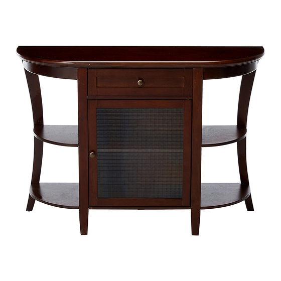
Style# C1293 Console
Style# C1293 Console
Page 1 of 12
Advertisement

Related Manuals for 2K Furniture Designs C1293


Summary of Contents for 2K Furniture Designs C1293
- Page 1 ASSEMBLY INSTRUCTIONS Style# C1293 Console Style# C1293 Console NOTE TO CUSTOMERS: • For ease and speed of assembly we recommend that before you commence each step of the assembly that you identify all the parts required to complete that step.
- Page 2 Page 2 of 12...
- Page 3 Quantity Quantity Quantity Quantity of 1 of 1 of 1 of 1 Bottom Panel Left Divider Right Divider Center Shelf Quantity Quantity Quantity Quantity of 1 of 1 of 1 of 1 Back Panel Left Shelf Left Shelf Top Panel Top Panel Right Shelf A11.
- Page 4 Quantity Quantity Quantity Quantity of 18 of 22 of 20 of 8 Camlock Wood Dowel Screw Screw Quantity Quantity Quantity Quantity Quantity of 10 of 10 of 2 of 4 of 1 Drawer Knob Screw Support Magnet Quantity Quantity Quantity Quantity of 1 of 1...
- Page 5 Step 1 Step 1 Step 1 1SET Attach Stopper B9 to Center Shelf A3 using including screws.(Hole is pre-drilled ) Step 2 4SETS 4PCS 1SET 1).Attach Magnet B8 to the bottom of Middle Shelf A3 using included Screws. Note:Holes are pre-drilled. 2).Assemble Dividers A1&A2 to Middle Shelf A3 using Wood Dowels B2 and Camlocks B1 Page 5 of 12...
- Page 6 Step 3 4SETS 4PCS 1).Assemble Shelf A5 to Dividers A1 using Wood Dowels B2 and Cam locks B1. 2).Assemble Shelf A6 to Dividers A2 using Wood Dowels B2 and Camlocks B1 . Step 4 4SETS 4PCS Assemble Bottom Panel A4 to Dividers A1&A2 using Wood Dowels B2 & Camlocks B1. Page 6 of 12...
- Page 7 Step 5 4PCS FRONT 1).Assemble Left Leg A9 to Bottom Panel A4 and Middle Shelf A5 using Screws B5. 2).Assemble Right Leg A10 to the Bottom Panel A4 and Middle Shelf A6 using Screws B5. 3).Attach Middle Legs A19 to Bottom Panel A4 as above drawing shown. Step 6 6SETS 6PCS...
- Page 8 Step 7 4PCS 6PCS FRONT Assemble Aprons A17&A18 to Top Panel A7 using Wood Dowels B2 and Screws B5. Note:Holes are pre-drilled. Step 8 20PCS Attach Back Panels A8 to the back of this unit using Screws B3. Page 8 of 12...
- Page 9 Step 9 4PCS 1).Insert Shelf Suports B7 into the holes on Dividers A1&A2. 2).Put Shelf A12 onto Shelf supports B7. Step 10 1SET 2PCS B10: Fig.2. Fig.1. 1). Insert Door Pin B10 into the hole on the bottom of Door A11, then connect Door A11 to Bottom Panel A7 as Fig.1.
- Page 10 Step 11 Step 11 8PCS 1SET 1). Assemble Drawer Side Panels A14 to Drawer Back Panel A15 using Screws B4. 2). Insert Drawer Bottom Panel A16 into the groo ves on Drawer Side Panels A14 and Drawer Back Panel A15. 3).
- Page 11 For your safety,please attach this unit to the wall by Anchor with Screw B11 and Anti-tip kit B12. Page 11 of 12...
- Page 12 APPENDIX: Dimension of Hardware in this AI. Cam-nut Cam-bolt B5&B11. B3&B8 Screw Screw Screw B12. Screw Screw Bolt for Handle Page 12 of 12...
Need help?
Do you have a question about the C1293 and is the answer not in the manual?
Questions and answers