Table of Contents
Advertisement
Quick Links
For questions or help with this product contact Tech Support at (570) 546-9663 or techsupport@grizzly.com
The following changes were recently made since the owner's manual was printed:
•
(3) EMERGENCY STOP buttons have been added to machine cabinet.
•
Magnetic switch parts have been updated to reflect change made in January, 2004.
•
Spindle switch parts have been updated to reflect change made in March, 2006.
Aside from this information, all other content in the owner's manual applies and MUST be read and under-
stood for your own safety. IMPORTANT: Keep this update with the owner's manual for future reference.
For questions or help, contact our Tech Support at (570) 546-9663 or techsupport@grizzly.com.
Revised Parts
101V2
55
54-1
54
54-2
54-3
82
REF PART #
DESCRIPTION
54
P9933054
EMERGENCY STOP BUTTON ASSEMBLY
54-1 P9933054-1 STOP BUTTON KEYON KB2-BE102
54-2 P9933054-2 BUTTON BASE
54-3 P9933054-3 TAP SCREW M4 X 42
55
P9933055
PHLP HD SCR M4-.7 X 8
82
P9933082
E-STOP BUTTON CORD 24G 2W 48"
WARNING: NO PORTION OF THIS MANUAL MAY BE REPRODUCED IN ANY SHAPE
OR FORM WITHOUT THE WRITTEN APPROVAL OF GRIZZLY INDUSTRIAL, INC.
READ THIS FIRST
164A
COPYRIGHT © MAY, 2022 BY GRIZZLY INDUSTRIAL, INC.
#CS22357 PRINTED IN TAIWAN
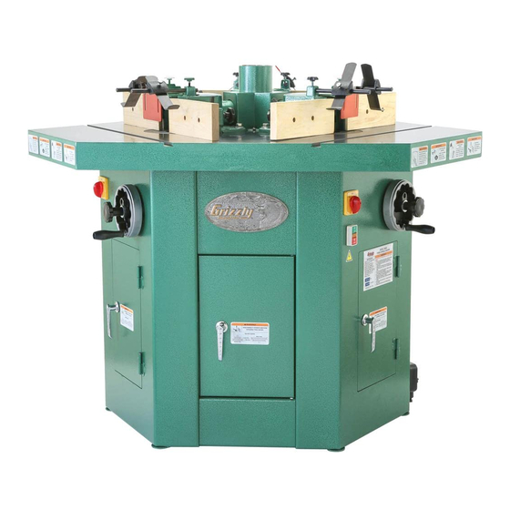
Model G9933
***IMPORTANT UPDATE***
For Machines Mfd. Since 05/22
and Owner's Manual Revised 05/09
179-2V2
179-1V2
REF
PART #
DESCRIPTION
101V2
P9933101V2
CABINET FRAME V2.05.22
164A
P9933164A
FWD/REV SWITCH V2.03.06
179-1V2 P9933179-1V2 OL RELAY NHD TH-12 12/18 V2.01.04
179-2V2 P9933179-2V2 CONTACTOR NHD C-12D10 220V V2.01.04
182V2
P9933182V2
MAG SWITCH BOX NHD V2.01.04
226V2
P9933226V2
MAG SWITCH ASSY NHD V2.01.04
226V2
182V2
Advertisement
Table of Contents

Related Manuals for Grizzly G9933


Summary of Contents for Grizzly G9933
- Page 1 ***IMPORTANT UPDATE*** For Machines Mfd. Since 05/22 and Owner's Manual Revised 05/09 For questions or help with this product contact Tech Support at (570) 546-9663 or techsupport@grizzly.com The following changes were recently made since the owner's manual was printed: •...
- Page 2 "how-to" book. 5. Twist EMERGENCY STOP buttons clockwise Connect an adequate dust collection system to until they spring out. This resets switches so the 4" central dust hood. Make sure the dust machine can start. hose is supported in a vertical position above the shaper table so that it is not in contact with any other part of the shaper and will not interfere with safe working conditions at each station. G9933 Update (Mfd. Since 05/22)
- Page 3 — If spindle rotates in opposite direction indicated by spindle switch, turn machine • V-belt tension (Page 38). OFF, disconnect power, then make sure station motor and magnetic switch are • Table insert adjustment (Page 41). wired correctly (refer to wiring diagrams beginning on Page 5 of this update). Fence alignment (Page 42). • G9933 Update (Mfd. Since 05/22)
- Page 4 EMERGENCY Read books/magazines or get formal train- STOP ing before beginning projects. Regardless Button of content, Grizzly Industrial will not be held liable for accidents due to lack of training. Figure 3. Power controls (station #1 shown). G9933 Update (Mfd. Since 05/22)
- Page 5 Table Top View Incoming Power Junction Box Station #1 Symbol Key: Main ON/OFF Switch Station Rotary Spindle Switch Station Station EMERGENCY Magnetic STOP Button Switch Station Motor READ ELECTRICAL SAFETY G9933 Update (Mfd. Since 05/22) ON PAGE 46 OF MANUAL!
- Page 6 EMERGENCY STOP EMERGENCY STOP Button Button 14NO Contactor NHD C-12D10 13NO To Station #2 Magnetic Switch 220V L6-30 Plug (As Recommended) Station Motor Incoming Power Junction Box Ground READ ELECTRICAL SAFETY G9933 Update (Mfd. Since 05/22) ON PAGE 46 OF MANUAL!
- Page 7 Station #2 Magnetic Switch Station #3 Magnetic Switch Overload Overload Relay Relay TH-12 TH-12 14NO 14NO Contactor Contactor NHD C-12D10 NHD C-12D10 13NO 13NO From Station #1 Magnetic Switch READ ELECTRICAL SAFETY G9933 Update (Mfd. Since 05/22) ON PAGE 46 OF MANUAL!
- Page 9 For Machines Mfd. Since 12/16 and Owner's Manual Revised 05/09 For questions or help with this product contact Tech Support at (570) 546-9663 or techsupport@grizzly.com The following change was recently made to this machine since the owner's manual was printed: •...
- Page 10 Tighten the safety jigs. knob bolts to secure the setting. Knob Bolts Extension Plate Spindle Guard Front Guard Figure 44. Extension plate and front guard attached to spindle guard. G9933 Update (Mfd. Since 12/16)
- Page 11 MODEL G9933 THREE SPINDLE SHAPER OWNER'S MANUAL WARNING: NO PORTION OF THIS MANUAL MAY BE REPRODUCED IN ANY SHAPE OR FORM WITHOUT THE WRITTEN APPROVAL OF GRIZZLY INDUSTRIAL, INC.
-
Page 13: Table Of Contents
Table of Contents INTRODUCTION ..........2 SECTION 5: ACCESSORIES ......34 SECTION 6: MAINTENANCE ......36 SECTION 1: SAFETY ........6 SECTION 7: SERVICE ........39 SECTION 2: CIRCUIT REQUIREMENTS ..9 SECTION 3: SETUP ........11 SECTION 8: WIRING ........46 SECTION 9: PARTS ........ -
Page 14: Introduction
INTRODUCTION Manual Accuracy Contact Info your machine may not exactly match the manual Machine Description www.grizzly.com... - Page 15 If you have never used this type of machine or equipment before, WE STRONGLY RECOMMEND that you read books, review industry trade magazines, or get formal training before beginning any projects. Regardless of the content in this section, Grizzly Industrial will not be held liable for accidents caused by lack of training.
- Page 16 Machine Data Sheet MACHINE DATA SHEET Customer Service #: (570) 546-9663 · To Order Call: (800) 523-4777 · Fax #: (800) 438-5901 MODEL G9933 THREE SPINDLE SHAPER Product Dimensions: Weight................................1185 lbs. Length/Width/Height......................... 45-1/2 x 52-1/8 x 45 in. Foot Print (Length/Width)......................... 37-1/4 x 34-1/4 in.
- Page 17 Table Info No. Of Table Inserts............................2 Table Insert Sizes I.D........................3-1/8, 6-1/4 in. Table Insert Sizes O.D.......................7-1/4, 9-3/16 in. Table Counterbore Diameter........................8-1/4 in. Table Counterbore Depth..........................3/8 in. Table Size Length..........................28-1/4 in. Table Size Width..........................21-3/4 in. Table Size Thickness........................... 3-1/16 in. Floor To Table Height..........................35 in.
-
Page 18: Section 1: Safety
SECTION 1: SAFETY For Your Own Safety, Read Instruction Manual Before Operating this Machine The purpose of safety symbols is to attract your attention to possible hazardous conditions. This manual uses a series of symbols and signal words intended to convey the level of importance of the safety messages. - Page 19 Safety Instructions for Machinery 7. ONLY ALLOW TRAINED AND PROP- 16. REMOVE CHUCK KEYS OR ADJUSTING ERLY SUPERVISED PERSONNEL TO TOOLS. OPERATE MACHINERY. 17. DAMAGED MACHINERY. 8. KEEP CHILDREN/VISITORS AWAY. 18. DO NOT FORCE MACHINERY. 9. UNATTENDED OPERATION. 19. SECURE WORKPIECE. 10.
- Page 20 Additional Safety Instructions for Shapers HAND POSITIONING. SHORT STOCK. KICKBACK HAZARD. MULTIPLE LIGHT PASSES. WORKPIECE CONDITION. SAFETY GUARDS & DEVICES. CUTTER CLEARANCE. 10. PUSH STICKS. RUB COLLARS. 11. SECURE COMPONENTS. Rub Collars Page 31 12. FEED RATE. BLIND CUT WHENEVER POSSIBLE. Like all machinery there is potential danger when operating this machine.
-
Page 21: Section 2: Circuit Requirements
SECTION 2: CIRCUIT REQUIREMENTS Minimum Cord Requirements 220V Single-Phase Operation Electrocution or fire could result if machine is not grounded and installed in compliance with electrical Power Connection Device codes. Compliance MUST be verified by a qualified electrician! Figure 2 Serious personal injury could occur if you connect the machine to power before com- pleting the setup process. - Page 22 Power Cord Connection Electrocution could result if you attempt to connect the incoming power wires to the machine when they are energized with power. ALWAYS make sure the Serious personal injury could occur if you incoming power wires are connect the machine to power before com- not connected to power pleting the setup process.
-
Page 23: Section 3: Setup
Wear safety glasses dur- ing the entire setup pro- cess! Unpacking The Model G9933 is a heavy machine. Serious personal injury may occur if safe moving methods are not used. To be safe, please imme-... - Page 24 Inventory Note: If you can't find an item on this list, check the mounting location on the machine or examine the packaging materials carefully. Occasionally we pre-install certain components for shipping purposes. Inventory: (Figures 5–6) Figure 5. Figure 6. SUFFOCATION HAZARD! Immediately discard all plas- tic bags and packing materi- als to eliminate choking/suf-...
- Page 25 Cleanup Gasoline and petroleum products have low flash points and can explode or cause fire if used to clean machinery. Avo i d u sing t h e s e p r o d u c t s to cl e a n machin e r y. Many cleaning solvents toxic inhaled.
- Page 26 Site Considerations Weight Load Physical Environment Machine Data Sheet Space Allocation Electrical Installation See below for working clearances. Lighting Children or untrained people may be seriously injured by this machine. Only install in an access restricted location. Table Base Cabinet Figure 8.
- Page 27 Bolting to Concrete Floors move the shipping crate and remove the machine from the crate. Figure 10 The Model G9933 can be lifted with one of the following methods: Lifting Straps & Safety Hooks: NOTICE Anchor studs are stronger and more per- Figure 9 manent alternatives to lag shield anchors;...
- Page 28 Using Machine Mounts Figure 11 Figure 13. Figures 14–15 Figure 11 Assembly To assemble your shaper: Figures 12–13 Figure 14. Note: There are two mounting positions for the guard assemblies. Position the assem- blies for the best protection from the cutter being used.
- Page 29 DO NOT operate the Model G9933 without various functions and safety features on an adequate dust collection system. This this machine.
- Page 30 Recommended Adjustments The Model G9933 shaper is designed to be used with only one motor operating at a time. Attempting to have more than one oper- ator using this machine at the same time may lead to an overload or cause seri-...
-
Page 31: Section 4: Operations
Failure to do so could result in serious per- training before beginning any projects. sonal injury, damage to equipment, or poor Regardless of the content in this section, work results. Grizzly Industrial will not be held liable for accidents caused by lack of training. - Page 32 Operation Overview Stock Inspection & Requirements Follow these rules when choosing and cutting stock: Operation Workpiece Material: To complete a typical operation, the operator does the following: Foreign Objects Large/Loose Knots Wet or "Green" Stock Excessive Warping Minor Warping...
- Page 33 Cutter Rotation Cutter Height Direction To change the cutter height: ALWAYS check the direction of the cut- ter rotation before beginning operation and ALWAYS feed the stock into the cutter AGAINST the cutter rotation. Feeding stock WITH the rotation of the cutter greatly could Figure 17 pull the workpiece from your hands and draw your hands into the spinning cutter,...
- Page 34 Hold-Downs Fence Adjustment Figure 18 Tools Needed Side-To-Side Fence Adjustment Figure 19 Figure 18. Figure 19. If the workpiece should rise up when it is against the cutter, kickback could occur. To reduce the chance of kickback and seri- ous personal injury, always properly secure the workpiece with the hold-downs during operation.
- Page 35 Changing Speeds Keep the fence opening around the cutter as small as possible without interfering with the cutter rotation. This configuration pro- vides the best support for the workpiece and reduces operator exposure to the spinning cutter during operation. In-Out Fence Adjustment Figure 19 Figure 20 Figure 19...
- Page 36 Figure 22 Figure 21 Figure 22. Figure 21. Figure 21 To avoid serious personal injury from entanglement and electrocution hazards, Note: The V-belt is properly tensioned when ALWAYS disconnect the there is approximately ⁄ " deflection between machine from power before the pulleys when moderate pressure is opening the cabinet doors applied, as illustrated in Figure 23.
- Page 37 Table Inserts Cutter Installation Figure 24 Accessories Page 34 Spindle Replacement Page 41 To ensure a safe and efficient operation, fol- low these rules when installing cutters: Table Insert Adjustment Page 41 Figure 24.
- Page 38 Figure 26 Installing Cutter Tools Needed To install a cutter: Figure 26. Figure 25 Note: The goal in the next steps is to install the cutter and spacers in a configuration that will keep the cutter as low as possible on the spindle.
- Page 39 Cutter Safety Guard CUTTING HAZARD! Cutters are sharp! Put on heavy leather gloves when handling a cutter or making adjustments near the cutter! Shaping Small Stock Page 29 Figure 28 Figure 28.
- Page 40 Edge Cutting Figure 29 Because the fence may not always be per- fectly parallel to the table miter slot, using the miter gauge could cause the workpiece to bind and kickback toward the operator. DO NOT use the miter gauge to feed the workpiece along the fence when straight shaping.
- Page 41 Cutting Rabbets Figure 30 Figure 32 Figure 30. Note: To reduce the effects of tearout, cut the end grain first when putting an edge around the perimeter of a workpiece, as illustrated in Figure 31. Figure 32. To make a rabbet cut: Figure 32 Note: To ensure good results for heavy cuts, make multiple light passes and raise the cut-...
- Page 42 Figure 33. To make a zero-clearance fence: The Model G9933 shaper is designed to be used with only one motor operating at a time. Attempting to have more than one oper-...
- Page 43 Rub collar above the cutter: Rub Collars Figure 35 Rub collars are used in one of the following positions: Figure 34 Figure 35. We DO NOT recommend using the rub Rub collar between two cutters: collar below the cutter. Figure Figure 34.
- Page 44 Irregular Shaping Freehand irregular shaping greatly increas- es the chance that the operator may lose con- trol of the workpiece, which could result in serious personal injury. Therefore, a pivot point Figure 38. MUST be used to control the workpiece while free- hand shaping.
- Page 45 When making a pattern, jig, or fixture, follow these guidelines: Figure 39 Figure 39.
-
Page 46: Section 5: Accessories
SECTION 5: ACCESSORIES ® G5562—SLIPIT 1 Qt. Gel H0783— ⁄ " Spindle G5563—SLIPIT ® 12 oz Spray H0784— ⁄ " Router Bit Spindle ® G2871—Boeshield T-9 12 oz Spray H0785— ⁄ " Collet for H0784 Router Spindle ® G2870—Boeshield T-9 4 oz Spray H3788—G96 ®... - Page 47 G4179— ⁄ HP Power Feeder Grizzly Industrial Spiral Cutterheads 4" Diameter, 1 ⁄ " Bore H2875—2" Height H2876—3 ⁄ " Height H2877—4" Height H2878—5 ⁄ " Height H2880—5 ⁄ " Height H2880—Carbide Insert Figure 43. G3642—Shop Fox Right Angle Jig Figure 45.
-
Page 48: Section 6: Maintenance
SECTION 6: MAINTENANCE Cleaning & Protecting Always disconnect power to the machine before performing maintenance. Failure to do this may result in serious person- al injury. Schedule Note: This maintenance schedule is based on average daily usage. Adjust the maintenance Section 5: Accessories Page 34 schedule to match your usage to keep your shaper... - Page 49 Lubrication Spindle Housing Figure 48 Worm Gear Figure 47 Figure 47. Figure 48.
- Page 50 V-Belt Tensioning & Replacement Note: The V-belt is properly tensioned when there is approximately ⁄ " deflection between the pulleys when moderate pressure is applied, as illustrated in Figure 50. Tensioning V-Belt Figure 49 Figure 50. Replacing V-Belt Steps 1–2 Figure 49.
-
Page 51: Section 7: Service
SECTION 7: SERVICE Troubleshooting Motor & Electrical Page 48 Page 38 Page 48 Page 38... - Page 52 Shaper Operations Page 37...
- Page 53 Table Insert Adjustment Note: Move the straightedge 360° around the spindle to ensure the entire insert surface is flush with the table in all directions. Spindle Replacement Tools Needed Tools Needed To adjust the outer insert: To replace the spindle: Figure 51 Figure 52 Figure 51.
- Page 54 Aligning Fence Figure 53 Figure 54 Correct Alignment Out of Alignment Figure 53 . Figure 54. Tools Needed To align the fences in the same plane: Figure 55 Figure 55.
- Page 55 Spindle Cartridge/ Bearing Figure 56 Replacement Tools Needed Figure 56. Figure 57 To replace the spindle cartridge or bearings: Figure 57. Steps 2–4...
- Page 56 Figure 58 Figure 60 Figure 58. Figure 60. Figure 59 Figure 61 Figure 59. Figure 61.
- Page 57 Figure 62 Figure 63 Note: Do not use a metal hammer on the spindle cartridge to avoid damaging the rim or threads. Note: The bearings are different sizes. Make sure to re-install them on the correct end of the spindle cartridge, as noted in Step 10.
-
Page 58: Section 8: Wiring
SHOCK HAZARD. MODIFICATIONS. MOTOR WIRING. QUALIFIED ELECTRICIAN. CAPACITORS. WIRE CONNECTIONS. CIRCUIT REQUIREMENTS. Page 9 WIRE/COMPONENT DAMAGE. EXPERIENCING DIFFICULTIES. The photos and diagrams included in this section are best viewed in color. You can view these pages in color at www.grizzly.com. - Page 59 Wiring Overview Station #3 Station #2 Table Top View Incoming Power Junction Box Station #1 Symbol Key: Main ON/OFF Switch Station Rotary Spindle Switch Station Motor Station Magnetic Switch READ ELECTRICAL SAFETY ON PAGE 46!
- Page 60 Wiring Diagram (A) Main Power Switch Station Rotary Spindle Switch Light WARNING! SHOCK HAZARD! Disconnect power before working on wiring. Station #1 Magnetic Switch Overload Relay Contactor Station Motor 220V L6-30 Plug (As Recommended) To Station #2 Magnetic Switch Incoming Power Junction Box READ ELECTRICAL SAFETY ON PAGE 46!
- Page 61 Wiring Diagram (B) To Station To Station Spindle Switch Spindle Switch & Motor & Motor Station #2 Magnetic Switch Station #3 Magnetic Switch Overload Overload Relay Relay Contactor Contactor From Station #1 Magnetic Switch...
-
Page 62: Section 9: Parts
SECTION 9: PARTS Motor & Spindle Breakdown... - Page 63 Motor & Spindle Parts List REF PART # DESCRIPTION REF PART # DESCRIPTION P9933001 OUTER SPINDLE HOUSING PW01M FLAT WASHER 8MM P9933002 GREASE CUP ASSEMBLY P9933050 THRUST WASHER PB01M HEX BOLT M10-1.5 X 30 P9933051 WORM GEAR PLW06M LOCK WASHER 10MM P9933052 THRUST WASHER PW04M...
- Page 64 MITER GAUGE ASSY P9933157 SPECIAL BOLT M8-1.25 X 80 P9933101 CABINET FRAME PN02 HEX NUT 5/16"-18 P9933102 LARGE DOOR G9987 GRIZZLY OVAL NAMEPLATE P9933104 SMALL DOOR PHTEK15M TAP SCREW M4 X 10 PN09M HEX NUT M12-1.75 P9933161 COMPRESSION SPRING PW06M...
- Page 65 Fence & Guard Assembly REF PART # DESCRIPTION REF PART # DESCRIPTION PSB14M CAP SCREW M8-1.25 X 20 PSS03M SET SCREW M6-1 X 8 P9933110 FENCE BOARD PW04M FLAT WASHER 10MM P9933111 FENCE RAIL PB32M HEX BOLT M10-1.5 X 25 P9933112 FENCE MOUNT PEC03M...
- Page 66 MUST maintain the original location and readability of the labels on the machine. If any label is removed or becomes unreadable, REPLACE that label before using the machine again. Contact Grizzly at (800) 523-4777 or www.grizzly.com to order new labels.
-
Page 69: Warranty And Returns
WARRANTY AND RETURNS... - Page 70 ® Buy Direct and Save with Grizzly – Trusted, Proven and a Great Value! ~Since 1983~ Visit Our Website Today For Current Specials! ORDER 24 HOURS A DAY! 1-800-523-4777...
Need help?
Do you have a question about the G9933 and is the answer not in the manual?
Questions and answers