Advertisement
User manual
SME1, SME2, SME5
Description
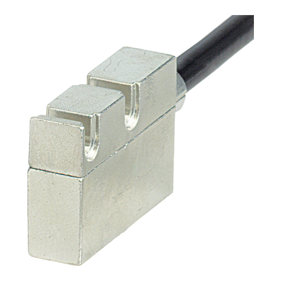
This manual describes products of the SME1, SME2,
SME5 series. The purpose of these sensors is to
measure linear or angular displacements on
industrial machines and automation systems. The
measurement system includes a magnetic tape and
a magnetic sensor. The tape has alternating
magnetic north/south poles are magnetized at a
certain distance called the pole pitch. As the sensor
is moved along the magnetic tape (or magnetic
ring), it detects the displacement and produces an
output signal equivalent to that of an incremental
encoder or a linear scale. The flexibility of the tape
allows it to be used for both linear and angular
applications.
The sensor has to be matched with the appropriated
magnetic tape (see chap. 2.1).
Chapters
1
Safety summary
2
Identification
3
Mounting instructions
4
Electrical connections
5
Output signals
6
Dimensional drawing
7
Maintenance
8
Troubleshooting
SME1 SME2 SME5
1 Safety summary
• observe the professional safety and accident prevention
regulations applicable to your country during device
installation and operation;
• installation has to be carried out by qualified personnel
only, without power supply and stationary mechanics
parts;
• the device must be used only for the purpose appropriate
to its design;
• high current, voltage and rotating parts can cause serious
or fatal injury.
• switch OFF the voltage before connecting the device;
• connect
connections";
• according to the 89/336/CEE norm on
electromagnetic
precautions must be taken:
before handling and installing, discharge electrical charge
from your body and tools which may come in touch with
the device;
power supply must be stable without noise, install EMC
filters on device power supply if needed;
always use shielded and twisted cables if possible;
avoid cables runs longer than necessary;
avoid running the signal cable near high voltage power
cables;
mount the device as far as possible from any capacitive or
inductive noise source, shield the device from noise source
if needed;
minimize noise by connecting shield and device housing to
ground (GND). Make sure that ground (GND) is not
affected by noise.
• install according to the section "Mounting instructions"
with stationary mechanics parts;
• do not disassemble the device;
• do not tool the device;
• do not subject the device to knocks or shocks;
• protect the system against solvents and substances
damaging it;
• respect the environmental characteristics of the product;
• be sure that the system is mounted where hard or sharp
objects (e.g. metal chips) do not come into contact with
the magnetic tape and the bottom of the sensor head. If
these conditions cannot be avoided provide a wiper or
pressurized air.
Safety
Electrical safety
according
to
instructions
compatibility,
following
Mechanical safety
of
"Electrical
Advertisement
Table of Contents

Summary of Contents for Lika SME1
- Page 1 • the device must be used only for the purpose appropriate to its design; This manual describes products of the SME1, SME2, • high current, voltage and rotating parts can cause serious SME5 series. The purpose of these sensors is to or fatal injury.
-
Page 2: Mounting Instructions
Avoid contact between the parts. You can edge of Reference Mark. check planarity and parallelism between sensor and magnetic tape using a feeler gauge SMEx LKM1309 SME1 LKM1309/1 0,1 0,3 mm 7,3 mm SME2 LKM1309/2 0,5 0,7 mm 7,5 mm SME5 LKM1309/5 0,5 1,0 mm... - Page 3 SME1 SME2 SME5 3.2 Mounting position with magnetic rings 3.3.1 Mounting position with magnetic rings and Reference “Z” Take care to the mounting of the sensor respect the magnetic ring. The arrow on the label showing "Reference pole” indicates the side of Reference “Z”.
-
Page 4: Electrical Connections
SME1 SME2 SME5 4 Electrical connections 4.1 Specifications of the cable Wires : 6 x 0.14mm + 2 x 0.24mm Colour Function Screening : Copper Yellow External Ø : Ø 5.2 mm ± 0.2 mm (Ø 0.2 in ± 0.01in) Blue Impedance : 6 x 145 Ω, 2 x 87 Ω... -
Page 5: Output Signals
SME1 SME2 SME5 5 Output signals 6 Dimensional drawing As the sensor is moved along the magnetic tape, it detects the displacement and produces an output signal equivalent to that of an incremental encoder or a linear scale. The signal output is proportional to the measuring speed and to the displacement of the sensor. -
Page 6: Troubleshooting
SME1 SME2 SME5 8 Troubleshooting The following list shows some typical errors that occur during installation and operation of the magnetic measurement system. Problem: The system doesn't work (no pulse output): • The tape or sensor has been mounted incorrectly (the active part of the tape doesn't face the sensor's active side). - Page 7 SME1 SME2 SME5 Man. Vers. Description 1st issue Revision of chap. 1, 3, 4, and 5 Revision of chap. 3.1 Revision of chap. 3.1 Revision of chap. 3.1 and 5.2...


Need help?
Do you have a question about the SME1 and is the answer not in the manual?
Questions and answers