Table of Contents
Advertisement
Quick Links
User manual
SME1, SME2, SME5
Chapters
1
Safety summary
2
Identification
3
Installation
4
5
6
7
8
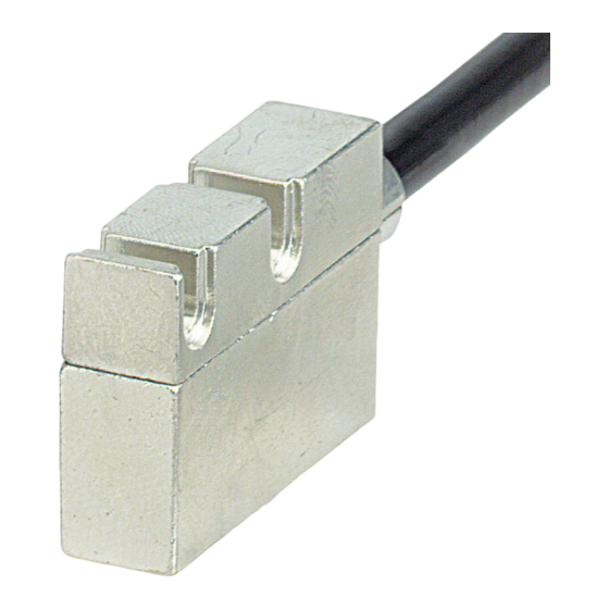
Description
This manual describes products of the SME1, SME2,
SME5 series. The purpose of these sensors is to
measure linear or angular displacements on
industrial machines and automation systems. The
measurement system includes a magnetic tape and
a magnetic sensor. The tape has alternating
magnetic north/south poles are magnetized at a
certain distance called the pole pitch. As the sensor
is moved along the magnetic tape (or magnetic
ring), it detects the displacement and produces an
output signal equivalent to that of an incremental
encoder or a linear scale. The flexibility of the tape
allows it to be used for both linear and angular
applications.
The sensor has to be matched with the appropriated
magnetic tape (see chap. 2.1).
1 - Safety summary
We strongly recommend carefully reading this user
manual and following the installation guidelines:
• Sensor head should be installed as close as
possible to your control unit.
• Always use shielded cables and twisted if
possible.
• Avoid running the sensor cable near high
voltage power cables (e.g. drive cables).
• Install EMC filters on sensor power supply if
needed.
• Avoid mounting sensor head near capacitive or
inductive noise sources such as relays, motors,
and switching power supplies.
Connect according to the supplied pin-out.
MAN SMEx I_E 1.0
SME1 – SME2 – SME5
2 - Identification
The sensor can be identified by the label's data
(ordering code, serial number). This information is
listed in the delivery document. All technical
features according to the ordering code are shown
on the catalogue.
2.1 Sensor and tape combinations
3 - Installation
Install the product according to the protection level
provided.
Protect the system against knocks, friction, solvents,
temperatures under -10°C (14°F) and over +70°C
(+158°F).
Be sure that the system is mounted where hard or
sharp objects (e.g. metal chips) do not come into
contact with the magnetic scale and the bottom of
the sensor head. If these conditions cannot be
avoided provide a wiper or pressurized air.
Sensor can be fixed by means of two M3 screws
over the buttonholes. Make sure that the gap
between sensor and tape is in respect with (fig. 8)
along the total measuring length. Avoid contact
between the parts. You can check planarity and
parallelism between sensor and magnetic tape using
a feeler gauge. The max. allowed gap (D) is listed in
chap. 2.1.
5
Sensor
Magnetic tape
SME1
SME2
SME5
MT10
MT20
MT50
www.lika.it
www.lika.biz
Advertisement
Table of Contents

Related Manuals for Lika SME1


Summary of Contents for Lika SME1
- Page 1 Description Install the product according to the protection level provided. This manual describes products of the SME1, SME2, Protect the system against knocks, friction, solvents, SME5 series. The purpose of these sensors is to temperatures under -10°C (14°F) and over +70°C measure linear or angular displacements on (+158°F).
- Page 2 SME1 – SME2 – SME5 3.1 Mounting tolerances 3.3 Mounting position with magnetic rings Sensor Sensor/Magnetic ring Sensor Sensor/Magnetic tape SME1 0,4 mm SME1 0,4 mm SME2 1,0 mm SME2 1,0 mm SME5 2,0 mm SME5 2,0 mm For mounting tolerances refer to paragraph 3.1 3.2 Mounting gap with Reference...
- Page 3 SME1 – SME2 – SME5 All our magnetic sensors can have A, /A, B, /B, 0, /0 4.2 Index “R” output signals. We recommend always connecting With ordering code "R" and in combination with the inverted signals if the receiving device will LKM-1309 accept them.
- Page 4 SME1 – SME2 – SME5 • The sensor touches the tape because tolerance 6 - Dimensional drawing gap between sensor and tape are not observed. Check sensor's active side if damaged. • The sensor has been damaged by short circuit or wrong connection.
Need help?
Do you have a question about the SME1 and is the answer not in the manual?
Questions and answers