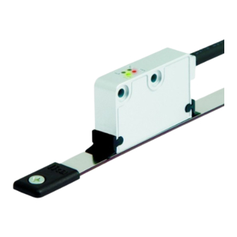
Lika SME11 User Manual
Hide thumbs
Also See for SME11:
- User manual (8 pages) ,
- Mounting instructions (2 pages) ,
- Manual (2 pages)
Advertisement
Available languages
Available languages
Quick Links
Advertisement

Subscribe to Our Youtube Channel
Summary of Contents for Lika SME11
- Page 2 Descrizione movimento; Il presente manuale è stato realizzato per descrivere utilizzare il dispositivo esclusivamente per la i prodotti SME11, SME21, SME51. Questi trasduttori funzione per cui è stato costruito: ogni altro di posizione sono stati progettati per realizzare utilizzo...
- Page 3 SME11 - SME21 - SME51 eventuali fonti di interferenza o schermarlo in 2.1 Abbinamento sensore / tipo di banda-anello maniera efficace; Abbinare obbligatoriamente il sensore al tipo di - per garantire un funzionamento corretto del banda o anello indicato sotto. Per maggiori...
- Page 4 SME11 - SME21 - SME51 visibile nella Figura 3 in quanto il sensore di 3.2 Montaggio sensore con banda magnetica Reference è posizionato lateralmente nella testina. La freccia (Figura 1 e Figura 6) indica la direzione di Fissare il sensore utilizzando due viti M3 a testa...
- Page 5 D1: distanza da rispettare tra sensore e LKM-1309. D2: distanza dal centro del foro di fissaggio al bordo del Reference. SMEx1 – LKM1309/x SME11 - LKM-1309/1 0,1 - 0,3 mm 7,3 mm SME21 - LKM-1309/2 0,5 - 0,7 mm 7,5 mm...
- Page 6 SME11 - SME21 - SME51 4 Connessioni elettriche 4.1 Caratteristiche del connettore ATTENZIONE Le connessioni elettriche devono essere Connettore M12 8 pin eseguite da personale qualificato, in maschio, lato contatti assenza di tensione e parti meccaniche Codifica A in movimento.
- Page 7 SME11 - SME21 - SME51 Istruzioni di montaggio“); ESEMPIO Errore 2: velocità di spostamento del Supponiamo di utilizzare l'encoder sensore sulla banda troppo elevata; lineare SME51-xx-x-50-... con banda velocità rotazione dell'anello MT50; dato che il passo del polo è di 5 troppo elevata (errore frequenza).
- Page 8 SME11 - SME21 - SME51 intendersi con movimento del sensore come è inviato contemporaneamente: il segnale di indicato dalla freccia nella Figura 1 nel caso di Reference è sincronizzato con i canali A e B applicazione lineare; con movimento dell'anello...
- Page 9 SME11 - SME21 - SME51 7 Risoluzione dei problemi Elenchiamo di seguito le cause tipiche di malfunzionamento riscontrabili durante l’installazione o l’uso del sistema di misura lineare Release Descrizione magnetico: Prima stampa Revisione generale Correzione sezione 3, revisione generale Errore: Aggiunto connettore M12 (sezione 4) Il sistema non conta.
-
Page 10: Table Of Contents
Description power supply disconnected and stationary This manual describes the products of the SME11, mechanical devices; SME21 and SME51 series. These encoders are device must be used only for the purpose... -
Page 11: Identification
SME11 - SME21 - SME51 capacitive or inductive noise source; shield the 2.1 Sensor and scale / ring combinations device from noise source if needed; The sensor has to be paired compulsorily with its - to guarantee a correct working of the device,... - Page 12 SME11 - SME21 - SME51 Reference sensor is located laterally in the sensing 3.2 Mounting the sensor with magnetic scale head. The sensor has to be fixed by means of two M3 15 The arrow (Figure 1 and Figure 6) indicates the mm min.
- Page 13 LKM-1309 external magnet. D2: distance from the centre of fixing hole to the edge of the Reference Mark. SMEx1 – LKM-1309/x SME11 - LKM-1309/1 0.1 – 0.3 mm 7.3 mm SME21 – LKM-1309/2 0.5 – 0.7 mm 7.5 mm SME51 - LKM-1309/5 0.5 – 1.0 mm 7.5 mm...
-
Page 14: Electrical Connections
SME11 - SME21 - SME51 4 Electrical connections 4.1 Connector specifications M12 8-pin connector WARNING male, frontal side Electrical connection has to be carried A coding out by qualified personnel only, with power supply disconnected mechanical parts compulsorily in stop. -
Page 15: Output Signals
SME11 - SME21 - SME51 met (pulse error), see the “3 - If you need to know the interpolation factor, then you have to divide the pole pitch value by the Mounting instructions“ section); resolution indicated in the order code. -
Page 16: Maintenance
SME11 - SME21 - SME51 shown in the Figure at the preferred location to NOTE mark a relevant position in the travel (the home The standard counting direction (the position, for instance). The R LED lights up when the channel A leads the channel B) is to be sensor detects the LKM-1309/X external reference. -
Page 17: Troubleshooting
SME11 - SME21 - SME51 Check the mounting tolerances between the sensor and the magnetic scale / ring all along the measuring length. Wear of the machine may increase the tolerances. Release Description The surface of the magnetic scale / ring should...


Need help?
Do you have a question about the SME11 and is the answer not in the manual?
Questions and answers