Advertisement
Available languages
Available languages
Quick Links
since 1975
S.I.R.I s.r.l.
Via R.Dalla Costa, 44/46
41122 MODENA (ITALY)
Tel. 059/313191 - Fax 059/311362
Email: info@siri.mo.it
http//www.siri.mo.it
SIRIPRO
57 – 68 – 80 – 90
130 - 160
MANUALE D'USO E MANUTENZIONE
OPERATING AND MAINTENANCE MANUAL
MANUEL D' EMPLOI ET ENTRETIEN
BEDIENUNGS UND WARTUNGSHANDBUCH
1
Advertisement

Related Manuals for SIRI SIRIPRO 57

Summary of Contents for SIRI SIRIPRO 57
- Page 1 1975 S.I.R.I s.r.l. Via R.Dalla Costa, 44/46 41122 MODENA (ITALY) Tel. 059/313191 - Fax 059/311362 Email: info@siri.mo.it http//www.siri.mo.it SIRIPRO 57 – 68 – 80 – 90 130 - 160 MANUALE D’USO E MANUTENZIONE OPERATING AND MAINTENANCE MANUAL MANUEL D’ EMPLOI ET ENTRETIEN...
- Page 2 SIRI PRO 57-68-80-90-130-160 Fig.1 Fig.2...
- Page 3 Manuale d’uso e manutenzione Ver 6.0 SIRI PRO 57-68-80-90-130-160 Fig.3 Fig. 4 Fig. 5...
- Page 4 FIG.6 FIG 7 FIG 7.1 FIG 8 FIG.9 FIG 9.1 FIG 10 FIG 11 FIG 11.1 FIG 12...
- Page 5 SIRI PRO 57-68-80-90-130-160 Manuale d’uso e manutenzione Ver 6.0 ART. 57 cm 40 x 40 cm 15 mm SIRI PRO 57 (art. 20057) SIRI PRO 68 68 cm 48 x 48 cm 15 mm (art. 20068) SIRI PRO 80 80 cm...
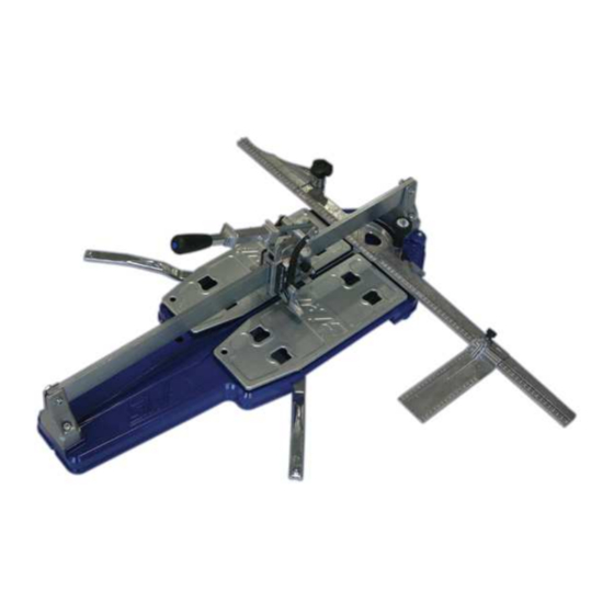
- Page 6 Manuale d’uso e manutenzione Ver 6.0 SIRI PRO 57-68-80-90-130-160 COMPONENTI DELLA TAGLIAPIASTRELLE (Fig.2) La macchina è nei suoi elementi principali così composta: 1) Base 2) Asta di scorrimento 3) Manico 4) Squadro 5) Prolunga 6) Squadretto MONTAGGIO TAGLIAPIASTRELLE La taglia piastrelle viene consegnata al Cliente all’interno dell’apposito cartone o valigetta (optional).
- Page 7 Manuale d’uso e manutenzione Ver 6.0 SIRI PRO 57-68-80-90-130-160 INCISIONE E ROTTURA A 45° (tagli diagonali) Per effettuare tale tipo di incisione occorre allentare il pomello (A) di Fig.2 e ruotare lo squadro fino a battuta contro l’apposito fermo e bloccarne la posizione serrando il pomello fig.10...
- Page 8 Operating and Maintenance manual Ver 6.0 SIRI PRO 57-68-80-90-130-160 TILE CUTTER COMPONENTS (Fig. 2) The machine basically consists of: 1) Base 2) Sliding rod 3) Handle 4) Square 5) Extension 6) Small square FITTING TILE CUTTER The tile cutter is delivered to the customer inside a box, as shown in Fig.2 or in a case (optional).
- Page 9 Operating and Maintenance manual Ver 6.0 SIRI PRO 57-68-80-90-130-160 INCISION AND BREAKING AT 45° (diagonal cuts) To make this type of incision, loosen the knob (A) of Pic.2, rotate the square until it makes contact with the stops and lock it in position by tightening the knob Pic 10 .
- Page 10 Manuel d’emploi et entretien Ver 6.0 SIRI PRO 57-68-80-90-130-160 COMPOSITION DU COUPE-CARREAUX (Fig. 2) Les principaux éléments du coupe-carreaux sont : 1) le châssis 2) la barre de glissement 3) la poignée 4) la règle graduée 5) Rallonge latérale 6) Petit équerre MONTAGE DU COUPE-CARREAUX Le coupe-carreaux est livré...
- Page 11 Manuel d’emploi et entretien Ver 6.0 SIRI PRO 57-68-80-90-130-160 COUPE ET CASSURE A 45° (coupes diagonales) Pour ce type de coupe, il faut dévisser le pommeau (A) de la Fig. 2 et tournez la règle graduée jusqu’ elle touche les butées et bloquez la position en vissant le pommeau Fig.
- Page 12 Bedienungs und wartungshandbuch Ver 6.0 SIRI PRO 57-68-80-90-130-160 BESTANDTEILE DER FLIESENSCHNEIDEMASCHINE (Abb.1) BEDIENUNGS UND WARTUNGSHANDBUCH Die wesentlichen Bestandteile der Maschine sind: 1) Untergestell 2) Gleitstange 3) Griff 4) Winkelanschlag 5) Verlängerung 6) Kleines Winkelstück MONTAGE DER FLIESENSCHNEIDEMASCHINE Die Fliesenschneidemaschine wird dem Kunden wie in einem Karton oder einem Koffer (OPTION) geliefert.
- Page 13 Bedienungs und wartungshandbuch Ver 6.0 SIRI PRO 57-68-80-90-130-160 45°-SCHNITT UND –BRUCH (Diagonalschnitte) Für diesen Schnitt den Knopf (A) Abb. 2 lockern und den Feststeller im Uhrzeigersinn drehen. Den Winkelanschlag bis zum Anschlag gegen die entsprechenden Feststeller drehen und durch Spannen des Knopfs in dieser Position blockieren. Abb.10 Die Fliese auf das Untergestell positionieren und unter Verwendung (4) der vorhandenen Millimeterskalen mit Winkelanschlag und Hilfswinkel (6) in Berührung bringen.
- Page 16 1975 S.I.R.I s.r.l. Via R.Dalla Costa, 44/46 41122 MODENA (ITALY) Tel. 059/313191 - Fax 059/311362 Email: info@siri.mo.it http//www.siri.mo.it...
Need help?
Do you have a question about the SIRIPRO 57 and is the answer not in the manual?
Questions and answers