Table of Contents
Advertisement
Quick Links
Questo manuale d'istruzione è fornito da trovaprezzi.it. Scopri tutte le offerte per
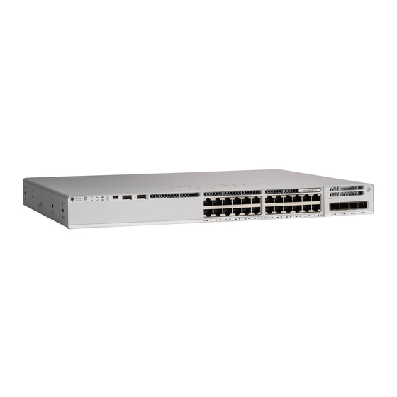
C9200-L C9200L-24PXG-4X-E
Cisco Catalyst 9200 Series Switches Hardware Installation Guide
First Published: 2018-11-19
Last Modified: 2020-11-17
Americas Headquarters
Cisco Systems, Inc.
170 West Tasman Drive
San Jose, CA 95134-1706
USA
http://www.cisco.com
Tel: 408 526-4000
800 553-NETS (6387)
Fax: 408 527-0883
o cerca il tuo prodotto tra le
migliori offerte di Switch
Cisco Catalyst
Advertisement
Table of Contents

Subscribe to Our Youtube Channel
Related Manuals for Cisco Catalyst C9200L-24PXG-4X-E


Summary of Contents for Cisco Catalyst C9200L-24PXG-4X-E
- Page 1 Questo manuale d’istruzione è fornito da trovaprezzi.it. Scopri tutte le offerte per Cisco Catalyst C9200-L C9200L-24PXG-4X-E o cerca il tuo prodotto tra le migliori offerte di Switch Cisco Catalyst 9200 Series Switches Hardware Installation Guide First Published: 2018-11-19 Last Modified: 2020-11-17 Americas Headquarters Cisco Systems, Inc.
- Page 2 © 2018–2020 Cisco Systems, Inc. All rights reserved.
-
Page 3: Table Of Contents
C H A P T E R 2 Installing the Switch Preparing for Installation Safety Warnings Installation Guidelines Shipping Box Contents Tools and Equipment Verifying Switch Operation Planning a Switch Data Stack Cisco Catalyst 9200 Series Switches Hardware Installation Guide... - Page 4 Finding the Power Supply Module Serial Number Installation Guidelines Installing or Replacing an AC Power Supply Module C H A P T E R 5 Installing a Fan Module Fan Modules Overview Cisco Catalyst 9200 Series Switches Hardware Installation Guide...
- Page 5 Accessing the CLI Through the Console Port Connecting the RJ-45 Console Port Connecting the USB Console Port Installing the Cisco Microsoft Windows USB Device Driver Installing the Cisco Microsoft Windows 7 USB Driver Uninstalling the Cisco Microsoft Windows USB Driver...
- Page 6 Contents Cisco Catalyst 9200 Series Switches Hardware Installation Guide...
-
Page 7: Product Overview
Network Configurations, on page 13 Switch Models The Cisco Catalyst 9200 Series switches have four modular (C9200) and eight fixed (C9200L) switch models. The following tables describe all the available Cisco Catalyst 9200 Series switches and the features supported. Table 1: C9200L Switch Models and Descriptions... - Page 8 2 power supply slots; 2 field-replaceable fans; supports StackWise-160. C9200-48T Stackable 48x1G ports; 4x1G and 4x10G network modules for uplink ports; 2 power supply slots; 2 field-replaceable fans; supports StackWise-160. Cisco Catalyst 9200 Series Switches Hardware Installation Guide...
-
Page 9: Front Panel Components
4x10G network modules for uplink ports; 2 power supply slots; 2 field-replaceable fans; supports StackWise-160. Front Panel Components This section describes the front panel components of Cisco Catalyst 9200 Series switches : • 24 or 48 downlink ports of one of the following types: • 10/100/1000 •... -
Page 10: 10/100/1000 Ports
• PoE/PoE+ ports: Support for IEEE 802.3af-compliant powered devices (up to 15.4W PoE per port) and support for IEEE 802.3at-compliant powered devices (up to 30W PoE+ per port). • Support for pre-standard Cisco powered devices. • Configurable support for Cisco intelligent power management, including enhanced power negotiation, power reservation, and per-port power policing. See the... -
Page 11: Multigigabit Ethernet Ports
RJ-45 console interface speeds. If you use the USB mini-Type B console port, the Cisco Windows USB device driver must be installed on any PC connected to the console port (for operation with Microsoft Windows). Mac OS X or Linux do not require special drivers. -
Page 12: Usb Type A Port
The port supports Cisco USB flash drives with capacities from 128 MB to 8 GB. USB devices with port densities of 128 MB, 256 MB, 1 GB, 4 GB, and 8 GB are supported. When combined with stacking, you can upgrade other switches in the stack from an USB key inserted in any switch within the stack. - Page 13 Module, on page Figure 4: Network Module C9200-NM-4G Module slot LEDs The following table lists the optional Cisco Catalyst 9200 Series Switches uplink network modules with 4x1G, 4x10G, 2x25G, and 2x40G slots. Table 3: Supported Network Modules Network Module Description C9200-NM-4G This module has four 1G SFP module slots.
-
Page 14: Rear Panel
Figure 5: Rear Panel of a C9200L Switch RJ-45 console port Blue Beacon LED Fixed fan modules on MGMT (RJ-45 C9200L switches 10/100/1000 management port) Power supply module StackWise-80 port slots connectors Cisco Catalyst 9200 Series Switches Hardware Installation Guide... -
Page 15: Rfid Tag
Connecting to the StackWise Ports, on page Caution Use only approved cables, and connect only to similar Cisco equipment. Equipment might be damaged if connected to nonapproved Cisco cables or equipment. Power Supply Modules The switch has a field replaceable main AC power supply module and a redundant hot-swappable field replaceable AC power supply module. - Page 16 Product Overview Power Supply Modules Following are the power supply modules supported on Cisco Catalyst 9200 Series Switches: • PWR-C5-125WAC • PWR-C5-600WAC • PWR-C5-1KWAC • PWR-C6-125WAC • PWR-C6-600WAC • PWR-C6-1KWAC The switch has two internal power supply module slots. You can use two AC power supply modules or one power supply module and a blank module (PWR-C5-BLANK).
- Page 17 C9200L-48PL-4G PWR-C5-600WAC 370W 740W C9200L-48PL-4X PWR-C5-600WAC 370W 740W C9200L-48PXG-2Y PWR-C5-1KWAC 740W 1440W C9200L-48PXG-4X PWR-C5-1KWAC 740W 1440W C9200L-48T-4G PWR-C5-125WAC — — C9200L-48T-4X PWR-C5-125WAC — — The power supply modules have two status LEDs. Cisco Catalyst 9200 Series Switches Hardware Installation Guide...
-
Page 18: Fan Modules
Power output to switch active. Output has failed. Fan Modules The Cisco Catalyst 9200 Series Switches supports two internal fixed 12-V fan modules and two field-replaceable fan modules (C9200-FAN=). The C9200 models support modular fans whereas the C9200L models provide two internal fixed fans. -
Page 19: Rj-45 Console Port
See the switch software configuration guide for network configuration concepts and examples of using the switch to create dedicated network segments and interconnecting the segments through Fast Ethernet and Gigabit Ethernet connections. Cisco Catalyst 9200 Series Switches Hardware Installation Guide... - Page 20 Product Overview Network Configurations Cisco Catalyst 9200 Series Switches Hardware Installation Guide...
-
Page 21: Installing The Switch
Ethernet cables must be shielded when used in a central office environment. Statement 171 Warning Do not work on the system or connect or disconnect cables during periods of lightning activity. Statement 1001 Cisco Catalyst 9200 Series Switches Hardware Installation Guide... - Page 22 Installation of the equipment must comply with local and national electrical codes. Statement 1074 Warning To prevent airflow restriction, allow clearance around the ventilation openings to be at least: 3 inches (7.6 cm). Statement 1076 Cisco Catalyst 9200 Series Switches Hardware Installation Guide...
-
Page 23: Installation Guidelines
Some components are optional, depending on your order. Note Verify that you have received these items. If any item is missing or damaged, contact your Cisco representative or reseller for instructions. Verify that you have received these items. If any item is missing or damaged, contact your Cisco representative or reseller for instructions. -
Page 24: Tools And Equipment
Before you install the switch in a rack or on a table or shelf, power on the switch and verify that it passes POST. To power on the switch, plug one end of the AC power cord into the switch AC power connector, and plug the other end into an AC power outlet. Cisco Catalyst 9200 Series Switches Hardware Installation Guide... -
Page 25: Planning A Switch Data Stack
• Number of switches in the stack. You can create data stacks with up to eight switches in a stack. • Length of the cable. Order the appropriate cable from your Cisco sales representative. The length of the cable depends on your configuration. These are the different sizes available: •... -
Page 26: Data Stack Cabling Configurations
This is an example of a recommended configuration that uses the supplied 0.5-meter StackWise cable. In this example, the switches are stacked in a vertical rack or on a table. This configuration provides redundant Cisco Catalyst 9200 Series Switches Hardware Installation Guide... -
Page 27: Data Stack Bandwidth And Partitioning Examples
Figure 11: Example of a Data Stack with Full Bandwidth Connections This figure shows an example of a stack of switches with incomplete StackWise cabling connections. This stack provides only half bandwidth and does not have redundant connections. Cisco Catalyst 9200 Series Switches Hardware Installation Guide... - Page 28 If the bottom switch is a member (not active or standby switch), it reloads. Figure 14: Example of a Partitioned Data Stack with a Failover Condition Cisco Catalyst 9200 Series Switches Hardware Installation Guide...
-
Page 29: Power-On Sequence For Switch Stacks
For conditions that can cause a stack reelection or to manually elect the active switch, see the stacking software configuration guide Stack Manager and High Availability Configuration Guide for Cisco Catalyst 9200 Series Switches on Cisco.com. -
Page 30: Mounting The Switch
Statement 1006 Figure 15: Rack-Mounting Brackets This figure shows the standard 19-inch brackets and other optional mounting brackets. You can order the optional brackets (ACC-KIT-T1=) from your Cisco sales representative. Cisco Catalyst 9200 Series Switches Hardware Installation Guide... -
Page 31: Attaching The Rack-Mount Brackets
Use two Phillips flat-head screws to attach the long side of the bracket to each side of the switch for the front- or rear-mounting positions. The following illustration shows a C9200L switch. C9200 switches follow the same method for installing the rack mount bracket. Cisco Catalyst 9200 Series Switches Hardware Installation Guide... - Page 32 Attaching the Rack-Mount Brackets Figure 16: Attaching Brackets for 19-inch Racks in a two-post rack front-mount position Figure 17: Attaching Brackets for 19-inch Racks in a two-post rack rear-mount position Number-8 Phillips flat-head screws Cisco Catalyst 9200 Series Switches Hardware Installation Guide...
-
Page 33: Mounting The Switch In A Rack
To install the switch on a table or shelf, locate the adhesive strip with the rubber feet in the mounting-kit envelope. Step 2 Attach the four rubber feet to the four circular etches on the bottom of the chassis. Cisco Catalyst 9200 Series Switches Hardware Installation Guide... -
Page 34: After Switch Installation
• Verify port connectivity after connecting devices to the switch ports. The LED turns green when the switch and the attached device have a link. Cisco Catalyst 9200 Series Switches Hardware Installation Guide... -
Page 35: Connecting To The Stackwise Ports
Connect the cable to the StackWise port on the switch rear panel. a) Align the StackWise cable connector with the StackWise adapter in the StackWise port. b) Insert the StackWise cable connector into the StackWise port. Make sure that the Cisco logo is on the top side of the connector. - Page 36 (installing and removing it up to 200 times is supported). When you need to remove the StackWise cable from the connector, make sure to fully unscrew the correct screws. When the connectors are not being used, replace the dust covers. Cisco Catalyst 9200 Series Switches Hardware Installation Guide...
-
Page 37: Connecting Devices To The Ethernet Ports
The 10/100/1000 PoE and PoE+ ports have the same autonegotiation settings and cabling requirements that are described in the 10/100/1000 Ports, on page 4. These ports can provide PoE and PoE+ inline power. Cisco Catalyst 9200 Series Switches Hardware Installation Guide... - Page 38 PoE inline power supports devices compliant with the IEEE 802.3af standard, as well as prestandard Cisco IP Phones and Cisco Aironet Access Points. Each port can deliver up to 15.4 W of PoE. PoE+ inline power supports devices compliant with the IEEE 802.3at standard, by delivering up to 30 W of PoE+ power per port to all switch ports.
-
Page 39: Installing A Network Module
Safety Warnings This section includes the installation cautions and warnings. Translations of the safety warnings are available in the Regulatory Compliance and Safety Information for Cisco Catalyst 9200 Series Switches . Read this section before you install a network module. -
Page 40: Installing A Network Module
Note The switch generates logs when you insert or remove a network module with SFP/SFP+ slots. Use only supported network modules and Cisco pluggable transceivers. Each module has an internal serial EEPROM that is encoded with security information. The network module is hot-swappable. If you remove a module, replace it with another network module or a blank module. -
Page 41: Removing A Network Module
Attach an ESD-preventive wrist strap to your wrist and to an earth ground surface Do not remove the network module with connected cables or installed pluggable transceiver modules. Caution Always remove any cables and modules before you remove the network module. Cisco Catalyst 9200 Series Switches Hardware Installation Guide... -
Page 42: Finding The Network Module Serial Number
Place the module that you removed in an antistatic bag or other protective environment. Finding the Network Module Serial Number If you contact Cisco Technical Assistance regarding a network module, you need to know its serial number. Figure 23: Network Module Serial Number Location... -
Page 43: Installing And Removing Pluggable Transceiver Modules
Installing a Cisco Pluggable Transceiver Module Before you begin See the switch release notes on Cisco.com for the list of supported a Cisco pluggable transceiver modules (SFP, SFP, SFP28 and QSFP+ modules). Use only supported modules on the switch. For the latest information... - Page 44 If the module has a bale-clasp latch, close it to lock the transceiver module in place. Step 6 Remove the transceiver module dust plugs and save. Step 7 Connect the transceiver module cables. Figure 25: Installing a Transceiver Module in the Uplink Module Slot Cisco Catalyst 9200 Series Switches Hardware Installation Guide...
-
Page 45: Removing A Cisco Pluggable Transceiver Module
Step 5 Grasp the transceiver module and carefully remove it from the slot. Step 6 Place the transceiver module in an antistatic bag or other protective environment. Cisco Catalyst 9200 Series Switches Hardware Installation Guide... - Page 46 Installing a Network Module Removing a Cisco Pluggable Transceiver Module Cisco Catalyst 9200 Series Switches Hardware Installation Guide...
-
Page 47: Installing A Power Supply Unit
PWR-C6-125WAC 125 W AC power supply module PWR-C6-600WAC 600 W AC power supply module PWR-C6-1KWAC 1000 W AC power supply module PWR-C5-BLANK Blank cover 1. Supported from Cisco IOS XE Gibraltar 16.11.1. Cisco Catalyst 9200 Series Switches Hardware Installation Guide... - Page 48 AC power supply module has a power cord for connection to an AC power outlet. The modules use an 18-AWG power cord. The following illustrations show the power supply modules. Figure 26: 1000W AC Power Supply Cisco Catalyst 9200 Series Switches Hardware Installation Guide...
- Page 49 AC power cord connector PS OK LED If no power supply is installed in a power supply slot, install a power supply slot cover. Figure 28: Power Supply Slot Cover Release handles Retainer clips Cisco Catalyst 9200 Series Switches Hardware Installation Guide...
-
Page 50: Finding The Power Supply Module Serial Number
Finding the Power Supply Module Serial Number If you contact Cisco Technical Assistance regarding a power supply module, you need to know the serial number. See the following illustrations to find the serial number. You can also use the CLI to find out the serial number. -
Page 51: Installation Guidelines
Do not reach into a vacant slot or chassis while you install or remove a module. Exposed circuitry could constitute an energy hazard. Statement 206 Warning Only trained and qualified personnel should be allowed to install, replace, or service this equipment. Statement 1030 Cisco Catalyst 9200 Series Switches Hardware Installation Guide... -
Page 52: Installing Or Replacing An Ac Power Supply Module
Installing a Power Supply Unit Installing or Replacing an AC Power Supply Module Warning If a Cisco external power system is not connected to the switch, install the provided connector cover on the back of the switch. Statement 386 Installing or Replacing an AC Power Supply Module... - Page 53 Connect the power cord to the power supply and to an AC power outlet. Turn on the power at the power source. Step 8 Confirm that the power supply AC OK and PS OK LED are green. Cisco Catalyst 9200 Series Switches Hardware Installation Guide...
- Page 54 Installing a Power Supply Unit Installing or Replacing an AC Power Supply Module Cisco Catalyst 9200 Series Switches Hardware Installation Guide...
-
Page 55: Installing A Fan Module
Finding the Fan Module Serial Number, on page 51 Fan Modules Overview Cisco Catalyst 9200 (C9200) Series switches support two field-replaceable fan modules providing N+1 redundancy support. The switch should be able to operate at ambient temperature if one of the fans fails. -
Page 56: Installation Guidelines
When the fan is operating, a green LED is on in the top left corner of the fan. Figure 33: Installing a Fan Module Warning Do not reach into a vacant slot when installing or removing a module. Exposed circuitry is an energy hazard. Statement 206 Cisco Catalyst 9200 Series Switches Hardware Installation Guide... -
Page 57: Finding The Fan Module Serial Number
Finding the Fan Module Serial Number Finding the Fan Module Serial Number If you contact Cisco Technical Assistance regarding a fan module, you need to know the fan module serial number. See the following illustration to find the serial number. - Page 58 Installing a Fan Module Finding the Fan Module Serial Number Cisco Catalyst 9200 Series Switches Hardware Installation Guide...
-
Page 59: Configuring The Switch
Start the terminal-emulation program on the PC or the terminal. The program, frequently a PC application such as HyperTerminal or ProcommPlus, makes communication between the switch and your PC or terminal possible. Cisco Catalyst 9200 Series Switches Hardware Installation Guide... -
Page 60: Connecting The Usb Console Port
If you are connecting the switch USB console port to a Windows-based PC for the first time, install the USB driver. See Installing the Cisco Microsoft Windows USB Device Driver, on page Note USB Type A port on the switch provides file system support and is NOT a console port. See USB Type A Port section. -
Page 61: Installing The Cisco Microsoft Windows Usb Device Driver
Installing the Cisco Microsoft Windows 7 USB Driver Procedure Step 1 Obtain the Cisco USB console driver file from the Cisco.com web site and unzip it. You can download the driver file from the Cisco.com site for downloading the switch software. Note Step 2 If using 32-bit Windows 7, double-click the setup.exe file in the Windows_32 folder. - Page 62 Configuring the Switch Uninstalling the Cisco Microsoft Windows 7 USB Driver Cisco Catalyst 9200 Series Switches Hardware Installation Guide...
-
Page 63: Technical Specifications
23°F to 113°F (–5°C to 45°C) up to 5000 feet (1500m) 23°F to 104°F (–5°C to 40ºC) up to 10,000 feet (3000m) Storage temperature –40 to 158°F (–40 to 70°C) Relative humidity 10 to 90% (noncondensing) Cisco Catalyst 9200 Series Switches Hardware Installation Guide... - Page 64 1.73 x 17.5 x 12.9 in. (4.4 x 44.5 x 32.9 cm) C9200L-48P-4G C9200L-48P-4G 1.73 x 17.5 x 11.3 in. (4.4 x 44.5 x 28.8 cm) 1.73 x 17.5 x 12.9 in. (4.4 x 44.5 x 32.9 cm) C9200L-48P-4X C9200L-48P-4X Cisco Catalyst 9200 Series Switches Hardware Installation Guide...
- Page 65 11.5 lb (5.2 kg) C9200-24PXG 11.4 lb (5.15 kg) C9200-48PXG 11.9 lb (5.44 kg) C9200L-24T-4G 9.6 lb (4.35 kg) C9200L-24P-4G 10.4 lb (4.71 kg) C9200L-48T-4G 10 lb (4.53 kg) C9200L-48P-4G 10.6 lb (4.8 kg) Cisco Catalyst 9200 Series Switches Hardware Installation Guide...
- Page 66 Dimensions (H x D x W) The dimensions shown include the extraction handle and the keying feature. PWR-C5-125WAC 1.58 x 4.0 x 7.6 in. (40.1 X 101.6 X 193 mm) PWR-C5-600WAC PWR-C5-1KWAC PWR-C6-125WAC PWR-C6-600WAC PWR-C6-1KWAC Cisco Catalyst 9200 Series Switches Hardware Installation Guide...
-
Page 67: Specifications For The Power Supplies And Fans
Table 18: Fan Module Environmental and Physical Specifications Environmental Ranges Operating temperature 23 to 176°F (–5 to 80°C) Storage temperature –40 to 185°F (–40 to 85°C) up to 15,000 ft (4500 m) Cisco Catalyst 9200 Series Switches Hardware Installation Guide... - Page 68 Physical Specification Dimensions (H x D x W) 1.62 x 1.73 x 4.24 in. (4.11 x 4.39 x 10.76 cm) Weight (for three fans) 0.48 lb (0.21 kg) Operating Specification 20 cfm Airflow Cisco Catalyst 9200 Series Switches Hardware Installation Guide...
-
Page 69: Switch Leds
You can use the switch LEDs to monitor switch activity and its performance. Figure 35: Switch Front Panel LEDs Console LED The console LED indicates whether the USB console port or the bluetooth console is enabled. Cisco Catalyst 9200 Series Switches Hardware Installation Guide... -
Page 70: System Led
Switch is the stack's active switch or a standalone switch. Fast blinking green Switch is in stack standby mode. Amber An error occurred when the switch was selecting the stack's active switch, or another type of stack error occurred. Cisco Catalyst 9200 Series Switches Hardware Installation Guide... -
Page 71: Stack Led
Stack member 1 LED blinks green to show that this is switch 1 in the stack. Stack member 2 LED blinks green to show that this is switch 2 in the stack. Cisco Catalyst 9200 Series Switches Hardware Installation Guide... -
Page 72: Poe Led
Active The active switch status. STACK Stack member status Stack member status. StackWise port status The StackWise port status. See STACK LED, on page The PoE+ port status. The PoE+ port status. Cisco Catalyst 9200 Series Switches Hardware Installation Guide... - Page 73 The switch is the active switch. Amber Error during active switch election. Blinking green Switch is a standby member of a data stack and assumes active responsibilities if the current active switch fails. Cisco Catalyst 9200 Series Switches Hardware Installation Guide...
-
Page 74: Beacon Led
The blue beacon on the front panel is a button labeled UID, and on the back panel it is a LED labeled BEACON. Color/State Description Solid blue The operator has indicated that the system needs attention. Cisco Catalyst 9200 Series Switches Hardware Installation Guide... -
Page 75: Rj-45 Console Port Led
LED. • For QSFP+ ports, a 40G labeling nomenclature is used, where 40G = 40 Gigabit. The The G label appears to the left of the uplink port LED. Cisco Catalyst 9200 Series Switches Hardware Installation Guide... - Page 76 Link is off due to a fault or because it has exceeded a limit set in the switch software. Link faults occur when non-compliant cabling is connected to an SFP/SFP+ Caution port. Use only standard-compliant cabling to connect to Cisco SFP/SFP+ ports. You must remove from the network any cable or device that causes a link fault. Amber Link for the SFP/SFP+/SFP28/QSFP+ has been disabled.
- Page 77 Cisco has more than 200 offices worldwide. Addresses and phone numbers are listed on the Cisco website at www.cisco.com/go/offices. Cisco and the Cisco logo are trademarks or registered trademarks of Cisco and/or its affiliates in the U.S. and other countries. To view a list of Cisco trademarks, go to this URL: https://www.cisco.com/c/en/us/about/legal/trademarks.html.
Need help?
Do you have a question about the Catalyst C9200L-24PXG-4X-E and is the answer not in the manual?
Questions and answers