Table of Contents
Advertisement
Quick Links
Kelly KBL Brushless Motor Controller User's Manual
Kelly KBL Brushless Motor
Controller User's Manual
0
Devices Supported:
KBL24101X
KBL48151X
KBL24151X
KBL48221X
KBL24221X
KBL48301X
KBL24301X
KBL48401E
KBL24401X
KBL48501E
KBL36101X
KBL72101X
KBL36151X
KBL72151X
KBL36221X
KBL72221X
KBL36301X
KBL72301X
KBL48101X
KBL72401E
KBL72501E
KBL96151
KBL96201
KBL96251
V 3.4
Rev.3.4
July, 2022
Advertisement
Table of Contents

Related Manuals for Kelly KBL24101X


Summary of Contents for Kelly KBL24101X
- Page 1 Kelly KBL Brushless Motor Controller User’s Manual V 3.4 Kelly KBL Brushless Motor Controller User’s Manual Devices Supported: KBL24101X KBL48151X KBL72501E KBL96151 KBL24151X KBL48221X KBL24221X KBL48301X KBL96201 KBL96251 KBL24301X KBL48401E KBL24401X KBL48501E KBL36101X KBL72101X KBL36151X KBL72151X KBL36221X KBL72221X KBL36301X KBL72301X...
-
Page 2: Table Of Contents
Kelly KBL Brushless Motor Controller User’s Manual V 3.4 Contents Chapter 1 Introduction ................. 2 1.1 Overview ................... 2 Chapter 2 Features and Specifications ............3 2.1 General functions ................3 2.2 Features .................... 4 2.3 Specifications ..................5 2.4 Naming Regulations ................5 Chapter 3 Wiring and Installation .............. -
Page 3: Chapter 1 Introduction
Introduction 1.1 Overview This manual introduces the Kelly BLDC motor controllers‟ features, their installation and their maintenance. Read the manual carefully and thoroughly before using the controller. If you have any questions, please contact the support center of Kelly Controls, LLC. -
Page 4: Chapter 2 Features And Specifications
(7) Maximum reverse speed is configurable to half of max forward speed. (8) Configurable and programmable with a host computer though RS232 or USB. Provide free GUI which can run on Windows XP/2000, Windows 7 and Vista(recommend using Kelly Standard USB To RS232 Converter). -
Page 5: Features
Kelly KBL Brushless Motor Controller User’s Manual V 3.4 (22) 3 hall position sensor inputs. Open collector, pull up provided. (23) Optional CAN bus. CAN bus is not included in KBL controller. By default, if customer don‟t pay it. (24) Optional supply voltage 8-30V. -
Page 6: Specifications
•Boost Current, 10 seconds: 150A-550A, depending on the model. •Motor Current Limit, 1 minute: 100A-500A, depending on the model. •Motor Current Limit, continuous: 60A-200A, depending on the model. •Max Battery Current : Configurable. 2.4 Naming Regulations The naming regulations of Kelly BLDC motor controllers... - Page 7 Kelly KBL Brushless Motor Controller User’s Manual V 3.4 Kelly KBL General Brushless Motor Controller Model Peak Current Peak Current Continuous Battery Regen 10 seconds 1 minute Current Voltage Operating (Amp) (Amp) (Amp) (Volt) Voltage(Volt) KBL24101X 12-24 KBL24151X 12-24 KBL24221X...
-
Page 8: Chapter 3 Wiring And Installation
Kelly KBL Brushless Motor Controller User’s Manual V 3.4 Chapter 3 Wiring and Installation 3.1 Mounting the Controller The controller can be oriented in any position which should be as clean and dry as possible, if necessary, shielded with a cover to protect it from water and contaminants. - Page 9 Kelly KBL Brushless Motor Controller User’s Manual V 3.4 Height: 84 millimeters KBL-E mounting holes‟ dimensions (dimensions in millimeters) Figure 2:...
-
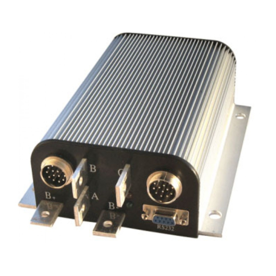
Page 10: Connections
Kelly KBL Brushless Motor Controller User’s Manual V 3.4 3.2 Connections 3.2.1 Front Panel of BLDC Motor Controller: Five metal bars and two plugs (J1, J2) are provided for connecting to the battery, motor and control signals in the front of the controller shown as Figure 3, 4 and 5. - Page 11 Kelly KBL Brushless Motor Controller User’s Manual V 3.4 Figure 5: The connecting diagram of J1 and J2 J1 Pin Definition 1- 12V 30mA.Only can be used for switch signals. 2- Current meter. <200mA 3- Main contactor driver. <2A To drive reverse beeper. <200mA...
- Page 12 Twist peripheral wires with PWR is the preferred for EMC. 3. Kelly Ammeter positive connect to 5V power supply of controller, negative to J1-2. 4. Switch to ground is active. Open switch is inactive.
- Page 13 Kelly KBL Brushless Motor Controller User’s Manual V 3.4 3.2.2 Wiring of BLDC Motor Controller Figure 6: Standard Wiring for Controllers Rated Equal or Lower Than 120V.
- Page 14 Kelly KBL Brushless Motor Controller User’s Manual V 3.4 Figure 7: BLDC controller preferred wiring (24V supply is preferred)
-
Page 15: Installation Check List
Kelly KBL Brushless Motor Controller User’s Manual V 3.4 3.2.3 Communication Port A RS232 port is provided to communicate with host computer for calibration and configuration. Figure 8: standard RS232 Interface 3.3 Installation Check List Before operating the vehicle, complete the following checkout procedures. Use LED code as a reference as listed in Table 1. -
Page 16: Chapter 4 Maintenance
conditions, but it doesn't affect programming or configuration. Use straight through RS232 cable or USB converter provided by Kelly to connect to a host computer. Provide >+18V to PWR (for a 24V controller, provide >+8V). Wire power supply return(supply negative) to any RTN pin. -
Page 17: Green Led Codes
Normal operation Green On Green & Red are both 1. Software still upgrading. 2. Supply voltage too low or battery too high 3. The controller is damaged. Contact Kelly about a warranty repair. Red LED Codes LED Code Explanation Solution Over voltage error ¤... - Page 18 Kelly KBL Brushless Motor Controller User’s Manual V 3.4 3. Controller is damaged. Contact Kelly about a warranty repair. Over temperature ¤¤ ¤¤¤ The controller temperature has exceeded 100℃. The controller will be stopped but will restart when temperature falls below 80℃.
- Page 19 Kelly KBL Brushless Motor Controller User’s Manual V 3.4 Table 2: KBL Controller CAN Commands List Version 1.1 You should specify when sending: ID:Our default ID is 0x6B, so only the data frame with ID 107 can be received by our controller.
- Page 20 Kelly KBL Brushless Motor Controller User’s Manual V 3.4 Command CCP_FLASH_READ Length data[0] 0xF2 data[1] CAL_TPS_DEAD_ZONE_HIGH data[2] Controller response Length data[0] TPS_Dead_Zone_High Desccription: Getting controller‟s Throttle high-end dead zone. CAL_TPS_DEAD_ZONE_HIGH constant is defined as 5. The maximum value of Throttle is 200. If the value of Throttle High-end Dead Zone is 160, indicating 80% high-end dead zone.
- Page 21 Kelly KBL Brushless Motor Controller User’s Manual V 3.4 Length data[0] 0x1a Controller response Length data[0] Ia A/D data[1] Ib A/D data[2] Ic A/D data[3] Va A/D data[4] Vb A/D data[5] Vc A/D Description: Data batch reading. 1) For Va, Vb, Vc, A/D value and voltage mapping relation is: V = Vad / 4.06.
- Page 22 Kelly KBL Brushless Motor Controller User’s Manual V 3.4 defined as 0. Command COM_SW_BRK Length data[0] 0x43 data[0] COM_READING Controller response Length data[0] Current Brake switch status Description: Getting Brake swith status, 1 – active, 0 – inactive. COM_READING constant is defined as 0.
-
Page 23: Contact Us
Kelly KBL Brushless Motor Controller User’s Manual V 3.4 Contact Us: Kelly Controls, LLC Home Page: http://www.KellyController.com E-mail: Support@KellyController.com Phone: (01) 224 637 5092...
Need help?
Do you have a question about the KBL24101X and is the answer not in the manual?
Questions and answers