Advertisement
Quick Links
Advertisement

Related Manuals for Hyster E210


Summary of Contents for Hyster E210
- Page 1 Hyster E210 (V30ZMD) Forklift...
- Page 2 ELECTRO-HYDRAULIC CONTROL VALVE J2.00-3.20XM (J40-65Z) [B416]; E1.50-2.00XM (E25-35Z, E40ZS) [F114]; E2.00-3.20XM (E45-65Z) [G108]; V30ZMD [E210]; E3.50-5.50XL, E4.50XLS (E70-120Z, E100ZS) [E098] PART NO. 1616865 2000 SRM 1224...
- Page 3 • Use the correct tools for the job. • Keep the tools clean and in good condition. • Always use HYSTER APPROVED parts when making repairs. Replacement parts must meet or exceed the specifications of the original equipment manufacturer. • Make sure all nuts, bolts, snap rings, and other fastening devices are removed before using force to remove parts.
- Page 4 Push Button Switch ..........................Joystick................................Remove and Disassemble.......................... Inspect................................ Assemble and Install..........................Troubleshooting..............................This section is for the following models: J2.00-3.20XM (J40-65Z) [B416]; E1.50-2.00XM (E25-35Z, E40ZS) [F114]; E2.00-3.20XM (E45-65Z) [G108]; V30ZMD [E210]; E3.50-5.50XL, E4.50XLS (E70-120Z, E100ZS) [E098] ©2008 HYSTER COMPANY...
- Page 5 Thanks very much for your reading, Want to get more information, Please click here, Then get the complete manual NOTE: If there is no response to click on the link above, please download the PDF document first, and then click on it. Have any questions please write to me: admin@servicemanualperfect.com...
- Page 6 "THE QUALITY KEEPERS" HYSTER APPROVED PARTS...
- Page 7 2000 SRM 1224 Description General This section has a description and the repair procedures for the Electro-Hydraulic control valve. Description ELECTRO-HYDRAULIC CONTROL SYSTEM The electro-hydraulic control system controls all hy- draulic functions, to include, lift/lower, tilt, and aux- iliary functions. The system consists of the following components: •...
- Page 8 MODULE 10. STEERING PUMP MOTOR 1. DRIVE AXLE Figure 2. Component Location E2.00-3.20XM 2. DRIVE WHEEL (E45-65Z) (G108); V30ZMD (E210) 3. ELECTRO-HYDRAULIC CONTROL VALVE 4. ELECTRO-HYDRAULIC VALVE DRIVER 5. MINI-LEVER HYDRAULIC CONTROL CONSOLE 6. HYDRAULIC TANK FILL 7. STEERING WHEEL 8.
- Page 9 2000 SRM 1224 Description Figure 4. Logic Diagram - Electro-Hydraulic Controls...
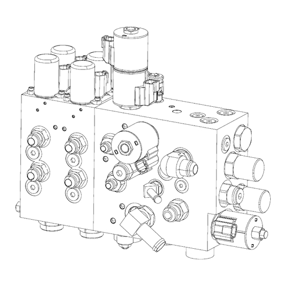
- Page 10 E100ZS) (E098) only 38 liter/min (10 gal/min) are available: • 3 function (single auxiliary) standard flow 23 liter/ min (6 gal/min) Figure 5. Electro-Hydraulic Control Valve Assembly for Lift Truck Models J2.00-3.20XM (J40-65Z) (B416), E2.00-3.20XM (E45-65Z) (G108), E1.50-2.00XM, E2.00XMS (E25-35Z, E40ZS) (F114), and V30ZMD (E210)
- Page 11 2000 SRM 1224 Description Legend for Figure 5 1. ELECTRO-HYDRAULIC PRESSURE REDUCING 17. SECONDARY RELIEF VALVE (SEE TABLE 1) VALVE (EHPR) 18. PROPORTIONAL PILOT-OPERATED VALVE 2. CARTRIDGE (TILT, STANDARD FLOW 19. CAPSCREW 20. AUXILIARY VALVE SECTION FUNCTIONS 3 AUXILIARY) 3. COIL RETAINING NUT AND 4 (HIGH FLOW) 4.
- Page 12 Description 2000 SRM 1224 1. PILOT OPERATED SOLENOID VALVE (EHPR) 15. FITTING 2. PRIORITY COMPENSATOR VALVE (EC1) 16. HOSE NIPPLE 3. PROPORTIONAL SOLENOID VALVE (SP1 AND 17. SECONDARY RELIEF VALVE (SEE TABLE 1) SP2) (RV2) 4. COIL (CL1) 18. SINGLE AUXILIARY VALVE SECTION (HIGH 5.
- Page 13 Valve Assembly 3 J2.00-3.20XM (J40-65Z) 22.7 MPa (3300 psi) 15.5 MPa (2250 psi) Function Standard Flow (B416), E2.00-3.20 (E45-65Z) (G108), V30ZMD (E210) Valve Assembly 4 E1.50-2.00XM 17.9 MPa (2600 psi) 15.5 MPa (2250 psi) Function Standard Flow (E25-35Z,E40ZS) (F114) Valve Assembly 4 J2.00-3.20XM (J40-65Z)
- Page 14 Description 2000 SRM 1224 The electro-hydraulic control valve is a fully-propor- The opening of the tilt solenoid valve combined with tional, closed centered valve. The circuit was de- the pump speed controls the velocity of the tilt func- signed for an on-demand variable pumping system. tion.
- Page 15 2000 SRM 1224 Description Figure 7. Electro-Hydraulic Control Valve Schematic (Standard Flow), all Trucks Except V30ZMD (E210) and E3.50-5.50XL, E4.50XLS (E70-120Z, E100ZS) (E098)
- Page 16 Description 2000 SRM 1224 Figure 8. Electro-Hydraulic Control Valve Schematic (High Flow) for Lift Truck Models J2.00-3.20XM (J40-65Z) (B416), E2.00-3.20XM (E45-65Z) (G108), and E1.50-2.00XM, E2.00XMS (E25-35Z, E40ZS) (F114)
- Page 17 2000 SRM 1224 Description Legend for Figure 8 1. PILOT-OPERATED SPOOL VALVE (PE1) 17. HYDRAULIC FILTER 2. PILOT-OPERATED SPOOL VALVE (PE2) 18. HYDRAULIC PUMP 3. TILT CYLINDERS 19. PRIMARY RELIEF VALVE (RV1) 4. LIFT CYLINDER 20. SECONDARY RELIEF VALVE (RV2) 5.
- Page 18 Description 2000 SRM 1224 Figure 9. Hydraulic Schematic With Electro-Hydraulics for Lift Truck Model V30ZMD (E210)
- Page 19 2000 SRM 1224 Description Legend for Figure 9 1. SINGLE ACTING PIVOT CYLINDER 19. LOWERING COMPENSATOR VALVE (EC2) 2. ADJUSTABLE FLOW RESTRICTOR 20. LOWERING SOLENOID VALVE WITH MANUAL 3. LOCK/CROSS OVER RELIEF VALVE OVERRIDE (SP2) 4. TRAVERSE HYDRAULIC MOTOR 21. PRIORITY COMPENSATOR VALVE (EC1) 5.
- Page 20 Description 2000 SRM 1224 1. PILOT-OPERATED SPOOL VALVE (PE1) 16. HYDRAULIC TANK (AUXILIARY 4) 17. HYDRAULIC FILTER 18. HYDRAULIC PUMP 2. PILOT-OPERATED SPOOL VALVE (PE2) (AUXILIARY 3) 19. PRIMARY RELIEF VALVE (RV1) 3. TILT CYLINDERS 20. SECONDARY RELIEF VALVE (RV2) 4.
- Page 21 2000 SRM 1224 Description The main control valve block contains the following • Lift Solenoid Valve (SP1): The Lift Solenoid Valve components: is a normally closed-proportional poppet valve. In- • Priority Compensator Valve (EC1): The priority creasing current in the coil opens the valve by caus- compensator is a load sensing priority on-demand ing the main poppet to lift.
- Page 22 E40ZS) V30ZMD (E210) (F114), E2.00-3.20XM (E45-65Z) (G108), and V30ZMD (E210), the tilt counterbalance valve is a semi-restrictive counterbalance valve with a 3:1 pilot ratio. The valve is designed to control over- running loads, as well as, hold loads in position at...
- Page 23 J2.00-3.20XM (J40-65Z) (B416), 1. TILT COUNTERBALANCE VALVE E1.50-2.00XM, E2.00XMS (E25-35Z, E40ZS) 2. O-RING (F114), E2.00-3.20XM (E45-65Z) (G108), and 3. BACKUP RING V30ZMD (E210) • Tilt Counterbalance Valve (CB1): For lift truck Figure 16. Tilt Counterbalance Valve for models E3.50-5.50XL, E4.50XLS (E70-120Z, Lift Truck Models E3.50-5.50XL, E4.50XLS...
- Page 24 (E098), the manual lowering valve is used to lower (E25-35Z, E40ZS) (F114), E2.00-3.20XM (E45-65Z) the load in the event of an electrical power failure. (G108), and V30ZMD (E210), the Lowering So- The manual lowering valve has a knob on the end lenoid Valve is a normally closed-proportional of the lowering solenoid valve shaft.
Need help?
Do you have a question about the E210 and is the answer not in the manual?
Questions and answers