
Related Manuals for allen AT16


Summary of Contents for allen AT16
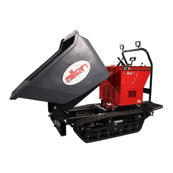
- Page 1 T R A C K B U G G I E S AT16 SAFETY & OPERATIONS MANUAL Man ual Par t #: 07 342 4 | R evis io n : B Languag e: E n g lish | O r igin a l In stru cti on s...
- Page 2 No part of this manual may be reproduced or transmitted in any form or by any means, electronics or mechanical, for any purpose, without the express written permission of Allen Engineering Corporation (AEC). AEC assumes no responsibility or liability for any errors or inaccuracies that may appear in this manual.
-
Page 3: Table Of Contents
Table of Contents GENERAL INFORMATION Sect No. Title Page Table of Contents ........................3 Limited Warranty ........................4 Information Contained in this Manual ..................5 Sound & Vibration Testing .......................6 Dealer Information / Ordering Parts ..................7 Model Number / Serial Number ....................8 Unit Identification ........................8 Technical Specifications ......................9 Engine Specifications ......................10 SAFETY ..........................11... -
Page 4: Limited Warranty
Allen reserves the choice to repair or replace. 2. If Allen chooses to replace the part, it will be at no cost to the customer and will be made available to the Allen Distributor, Dealer, or Rental Center from whom the End User purchased the product. -
Page 5: Information Contained In This Manual
Complete any warranty requirements as specified by the engine manufacturer in their instructions found inside the manual box located on the back of the riding trowel operator’s seat. Your engine and clutch is not manufactured by Allen Engineering Corporation, Inc, and therefore is not covered under Allen Engineering Corporation, Inc warranty. -
Page 6: Sound & Vibration Testing
Operator Ear SPL Seat Vibration Average Vibration Average Vibration Average - dB (A) - m/sec² - m/sec² - m/sec² This information was acquired from sound and vibration analysis tests conducted at Allen Engineering Corporation test facilities. PENDING INFORMATION Page 6 073424... -
Page 7: Dealer Information / Ordering Parts
INFORMATION Ordering Parts Your Dealer has Allen Engineering Corporation trained mechanics and original Allen replacement parts. Always contact the Allen Dealer who sold you this machine for Allen Certified repairs and replacement parts. Place Allen Dealer information below for future reference. -
Page 8: Model Number / Serial Number
The serial number found on the identification plate is a ten digit format. The model number identifies your machine and will ensure that you receive the correct replacement parts. Serial Number Example AT16 01 21 01 Sequence Number Year Month... -
Page 9: Technical Specifications
Technical Specifications GENERAL INFORMATION Measurements in this manual are in standard units Machine Features for: • Horse Power ..................25 • Fuel Capacity ..................6 Gal • Fuel Consumption (Approx.) ............1.3 GPH • Steering System ................. Hydraulic • Maximum Speed ................6 MPH •... -
Page 10: Engine Specifications
Engine Specifications GENERAL INFORMATION Kohler Engine Information Model: ..........EZT740 Fuel Type: . -
Page 11: Safety
SECTION 1 SAFETY SECTION 1: SAFETY 073424 Page 11... -
Page 12: Federal / State Warnings
Federal / State Warnings SECTION 1 SAFETY RESPIRATORY HAZARDS Grinding/cutting/drilling of masonry, concrete, metal and other materials can generate dust, mists and fumes containing chemicals known to cause serious or fatal injury or illness, such as respiratory disease, cancer, birth defects or other reproductive harm. SILICOSIS WARNING Grinding/cutting/drilling of masonry, concrete, metal and other materials with silica in their composition may... -
Page 13: Manual Tag Safety Detail
Manual Tag Safety Detail SECTION 1 SAFETY Safety-Alert Signs This manual contains Safety-Alert Signs, as defined below, which must be followed to reduce the possibility of improper servi ce damage to the equipment or personal injury. Read and follow all Safety-Alert Signs included in this manual. NOTE defines an operating procedure, condition, etc. -
Page 14: Hazard Symbols
Hazard Symbols SECTION 1 SAFETY Potential hazards associated with the operation of this equipment will be referenced with hazard symbols which may appear throughout this manual in conjunction with safety notes. Page 14 073424... -
Page 15: General Safety
General Safety SECTION 1 SAFETY Familiarity and proper training are required for the safe operation of this equipment! Equipment operated improperly or by untrained personnel can be dangerous! Read the operating instructions contained in both this manual and the engine manual and familiarize yourself with the location and proper use of all controls. •... -
Page 16: Engine Safety
Engine Safety SECTION 1 SAFETY Internal combustion engines present special hazards during operation and fueling. Read and follow the warning instructions in the engine owner’s manual and the safety guidelines below. Failure to follow the warnings and safety guidelines could result in severe injury or death. •... -
Page 17: Service Safety
Service Safety SECTION 1 SAFETY Poorly maintained equipment can become a safety hazard! In order for the equipment to operate safely and properly over a long period of time, periodic maintenance and occasional repairs are necessary. • ALWAYS disconnect the battery before servicing the equipment. •... -
Page 18: Lifting Safety
Lifting Safety SECTION 1 SAFETY ALWAYS DO A THOROUGH INSPECTION OF THE SLINGS, CHAINS, AND HOOKS BEFORE ATTEMPTING TO LIFT THE MACHINE! OSHA has set forth guidelines which detail the use of Rigging Equipment for Material handling. This guideline is found under OSHA Standard Number: 1926.251 Please read and follow all guidelines found in this standard. - Page 19 Lifting Safety SECTION 1 SAFETY • When lifting the machine, all personnel must be clear of the machine. • DO NOT stand near or under the machine while it is being lifted. Lifting instructions using a hoist: • Place slings, chains or hooks through each lifting point on the machine. Use a sling or chains connected to a central lifting device.
-
Page 20: Transportation Safety
Transportation Safety SECTION 1 SAFETY • Make sure the hitch and coupling of the towing vehicle are rated equal to, or greater than the trailer “gross vehicle weight rating.” • ALWAYS inspect the hitch and coupling for wear. Never tow a trailer with defective hitches, couplings, chains, etc. -
Page 21: Notes
Notes SECTION 1 SAFETY 073424 Page 21... -
Page 22: Operation
SECTION 2 OPERATION SECTION 2: OPERATION Page 22 073424... -
Page 23: Pre-Operation Instructions
Pre-Operation Instructions SECTION 2 OPERATION Before operation each day ensure the following: • All guards, side screens and panels are in place. • All safety and information signs are in place and legible. • Engine and hydraulic oil levels are correct. •... - Page 24 Pre-Operation Instructions SECTION 2 OPERATION Watch for conditions that could cause: • Loss of control • A collision • Tip-over Check overhead clearances. Know the size of doorways and canopies. Know exactly how much clearance you have under power lines and telephone lines. All local, state/provincial, and federal regulations must be met before approaching power lines, overhead or underground cables or other power sources with any part of your power buggy.
-
Page 25: Starting Instructions
Starting Instructions SECTION 2 OPERATION • Make sure that the parking brake is fully applied and in the locked position. • Make sure fuel valve is open on fuel tank. • Note: If engine is cold, move choke lever to close position. If engine is hot, set choke to open position. -
Page 26: Operating Instructions
Operating Instructions SECTION 2 OPERATION To drive and stop equipment: A. With parking brake engaged and directional control in center position, increase the engine speed to full throttle using the throttle lever on the left side of the control panel. B. - Page 27 Operating Instructions SECTION 2 OPERATION • Keep personnel clear of the buggy during travel. • Do not allow anyone to stand/pass in front of the buggy during travel. • Do not approach personnel standing in front of fixed objects. Do not allow others to ride on the buggy. •...
- Page 28 Operating Instructions SECTION 2 OPERATION • Do not ride on buggy if the buggy is to travel on uneven/rough terrain. Instead, raise and secure the platform and walk behind the buggy. Check to make certain that the mounting bolts are sufficiently tight to retain it in that position. Do not exceed creep speed.
-
Page 29: Service
SECTION 3 SERVICE SECTION 3: SERVICE 073424 Page 29... -
Page 30: Maintenance Instructions
Maintenance Instructions SECTION 3 SERVICE Maintenance described in this section represents minimum requirements for continuous satisfactory operation of the machine. Because improperly maintained machines are hazardous, it is extremely important that only qualified mechanics perform maintenance work. It is imperative that only genuine AEC parts are used if replacement is needed as substituted parts in critical areas may place the operator at risk. -
Page 31: Engine Oil Maintenance
Engine Oil Maintenance SECTION 3 SERVICE • Engine Oil Level Check ALWAYS check the engine oil dipstick before using the buggy. At a minimum check engine oil once per day. Follow the Maintenance and Lubrication Chart contained herein. • ALWAYS use a good quality engine oil. •... -
Page 32: Air Filter Maintenance
Air Filter Maintenance SECTION 3 SERVICE Pre-Cleaner Maintenance Procedure This engine is equipped with a large capacity, dual element air filter—an oiled, foam pre-cleaner surrounds a high density paper element. WING NUT COVER FOAM PRE-CLEANER PAPER ELEMENT ENGINE MEMBER Every 25 hours of operating time (more often under extremely dusty or dirty conditions) the oiled, foam pre-cleaner needs washing and oiling. - Page 33 Air Filter Maintenance SECTION 3 SERVICE Paper Element Maintenance Procedure Every 100 operating hours (more often under extremely dusty or dirty conditions) clean or replace the paper element as follows: • Raise the bucket. • Unlatch and remove the engine housing cover and access the air filter from the front. Remove wing nut, air filter cover and paper element with foam pre-cleaner.
-
Page 34: Scheduled Maintenance Times
Scheduled Maintenance Times SECTION 3 SERVICE Maintenance Schedule Item Daily Weekly Monthly Annually 100 Hours Check external hardware Check hydraulic oil level Check hydraulic fittings and hoses Apply grease to track rollers Apply grease to bucket hinge Check all operational controls Tighten all bolts and nuts. -
Page 35: Track Tension Adjustment
Track Tension Adjustment SECTION 3 SERVICE The track stretches during its life cycle and needs to be adjusted regularly. Hoist one side of the machine so that the buggy is parallel to the ground. Inspect the clearance between the track and the second wheel to be approximately 1/2” [12.7mm]. Adjust the tracks by loosening the lock nuts and tightening the adjustment bolt to the desired dimen- sion. -
Page 36: Filter Replacement
Filter Replacement SECTION 3 SERVICE AIR CLEANER PAPER ELEMENT PART #: - ENGINE OIL FILTER PART #: - ENGINE FUEL FILTER PART #: - HYDRAULIC OIL FILTER PART #: 046730 Page 36 073424... - Page 37 Filter Replacement SECTION 3 SERVICE FILTER MAINTENANCE KIT Includes: • Air filter: Part # - 057991 • Pre-cleaner: Part # - 057992 • Oil filter: Part # - 057994 • Fuel Filter: Part # - 057993 • 10W-30 Oil: Part # - N/A (qty: 2-quarts) •...
-
Page 38: Engine Belt Tension Adjustment
Engine Belt Tension Adjustment SECTION 3 SERVICE 1. To tension engine belts use the 2 engine belt tensioning bolts. (A) 2. Engine Belt Tensioning Specifications are 2-1/8”. Page 38 073424... - Page 39 Engine Belt Tension Adjustment SECTION 3 SERVICE 1. When tensioning engine belts place a tape measure on the Main Frame as pictured above. The end of the tape measure will rest against the engine block. 2. There is a recess in the Main Frame for the Engine plate as indicated in picture above with a yellow line.
-
Page 40: Auxiliary Belt Tension Adjustment
Auxiliary Belt Tension Adjustment SECTION 3 SERVICE 1. Place straight edge on the edge of the framework. Notice the arrows that point to the two half moon cut-outs in the framework, use the cut-outs as a guideline for tensioning the Auxiliary Pump. 2. - Page 41 Auxiliary Belt Tension Adjustment SECTION 3 SERVICE 1. Place a tape measure against the back side of cut-out and measure ½” to the corner edge of the pump mounting plate for desired Auxiliary Pump belt tension. 2. Auxiliary Pump Belt tension must be set before setting Engine / Transmission Drive belt tension.
-
Page 42: Troubleshooting
Troubleshooting SECTION 3 SERVICE Possible Corrective Area Malfunction Ref. Cause Measure - Add battery fluid Battery is discharged - Charge the battery - Replace the battery Battery cable is disconnected - Connect battery cable Blown fuse - Replace fuse Bad connection or breakage in the wiring - Contact your AEC dealer Out of fuel - Fill fuel... - Page 43 Troubleshooting SECTION 3 SERVICE Possible Corrective Area Malfunction Ref. Cause Measure Bad fuel - Change fuel Clogged air cleaner - Clean or replace the air cleaner Black smoke comes out of exhaust Choke is not fully open - Open the choke fully Engine Other (other than above) - Contact your AEC dealer...
-
Page 44: Cleaning Procedure
Cleaning Procedure SECTION 3 SERVICE Machine Cleaning Procedure When cleaning the machine, please adhere to the following information to ensure proper cleaning and to keep the machine in the best condition possible. Power Washing Procedure: • Ensure that the water pressure is below 2000 PSI (14 MPa) •... -
Page 45: Revision Detail
Revision Detail GENERAL INFORMATION MANUAL REVISION DETAIL REVISION # REVISION DATE REVISION REFERENCE # REVISION BY 04/21 Initial Release 01/22 Updated Covers 06/22 Manual Corrections 073424 Page 45... -
Page 46: Parts Manual
Click the link, or go to the following website https://www.alleneng.com/at16 Mail: A physical copy of the manual can also be mailed to you upon request. Please contact Allen Engineering and one will be sent to you. Allen Engineering P.O. Box 819 Paragould, Ar. - Page 48 AEC FACTORY & HEADQUARTERS 8 1 9 S . 5 T H S T R E E T P A R A G O U L D , A R K A N S A S 7 2 4 5 0 8 7 0 .
Need help?
Do you have a question about the AT16 and is the answer not in the manual?
Questions and answers