
Related Manuals for allen ATD3300


Summary of Contents for allen ATD3300
- Page 1 T R A C K D U M P E R ATD3300 SAFETY & OPERATIONS MANUAL Man ual Par t #: 07 925 7 | R evis io n : - Languag e: E n g lish | O r igin a l In stru cti on s...
- Page 2 No part of this manual may be reproduced or transmitted in any form or by any means, electronics or mechanical, for any purpose, without the express written permission of Allen Engineering Corporation (AEC). AEC assumes no responsibility or liability for any errors or inaccuracies that may appear in this manual.
-
Page 3: Table Of Contents
Table of Contents GENERAL INFORMATION Sect No. Title Page Table of Contents ..........................3 General Information and Limited Warranty & Limitation of Liability ............4 Dealer Information & Ordering Parts ....................5 Model & Serial Number / Unit Identification ..................6 Introduction &... -
Page 4: General Information And Limited Warranty & Limitation Of Liability
Allen reserves the choice to repair or replace. 2. If Allen chooses to replace the part, it will be at no cost to the customer and will be made available to the Allen Distributor, Dealer, or Rental Center from whom the End User purchased the product. -
Page 5: Dealer Information & Ordering Parts
GENERAL INFORMATION Your Dealer has Allen Engineering Corporation trained mechanics and original Allen replacement parts. Always contact the Allen Dealer who sold you this machine for Allen Certified repairs and replacement parts. Place Allen Dealer information below for future reference. -
Page 6: Model & Serial Number / Unit Identification
Model & Serial Number / Unit Identification GENERAL INFORMATION Manufacturer’s Codes: When ordering parts or requesting service information, you will always be asked to specify the model and serial numbers of the machine. The legends below specifically defines each significant character or group of characters of the Model Number and Serial Number codes. -
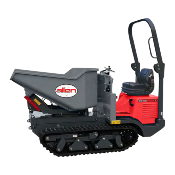
Page 7: Introduction & Machine Components
ATD3300 Track Dumper The ATD3300 has been designed in order to meet the needs of customers that operate in various fields. It is mainly used in the sectors in which loading, transportation and unloading of materials such as gravel, sand, building rubble, logs and wood loads for deforestation and forest conservation is required. -
Page 8: Technical Specifications
Technical Specifications GENERAL INFORMATION General Characteristics Max Payload 3,300 lb 1,497 kg On level road ( FWD/REV) 7.5 MPH 12 KPH Max Speed Up Hill (FWD/REV) 2.1 MPH 3.5 KPH Max Slope (Loaded) (Approximate slope %) Hydrostatic Drive System Variable Displacement Axial Piston Pumps Unitary Displacement 7.39 GAL/min... -
Page 9: Engine Specifications
Engine Specifications GENERAL INFORMATION General Specification Engine Kubota D902 Type Vertical, Water Cooled 4-cycle diesel engine Cylinders Bore and Stoke 72 x 73.6 mm (2.83 x 2.90 in) Displacement 0.898 L (54.80 cu in) 18.5 kW (24.8 HP) at 3600 rpm Combustion System Direct injection Fuel System... -
Page 10: Safety
SECTION 1 SAFETY SECTION 1: SAFETY Page 10 079256... -
Page 11: General Safety
General Safety SECTION 1 SAFETY Safety-Alert Signs This manual contains Safety-Alert Signs, as defined below, which must be followed to reduce the possibility of improper servi ce damage to the equipment or personal injury. Read and follow all Safety-Alert Signs included in this manual. NOTE defines an operating procedure, condition, etc. -
Page 12: Federal / State Warning Regulations
Federal / State Warning Regulations SECTION 1 SAFETY RESPIRATORY HAZARDS Grinding/cutting/drilling of masonry, concrete, metal and other materials can generate dust, mists and fumes con- taining chemicals known to cause serious or fatal injury or illness, such as respiratory disease, cancer, birth defects or other reproductive harm. -
Page 13: Engine Safety
Engine Safety SECTION 1 SAFETY Internal combustion engines present special hazards during operation and fueling. Read and follow the warning instructions in the engine owner’s manual and the safety guidelines below. Failure to follow the warnings and safety guidelines could result in severe injury or death. •... -
Page 14: General Safety
General Safety SECTION 1 SAFETY Carefully follow the safety warnings contained in the manual and applied on the vehicle; these signal a potential danger and point out the precautions to take to prevent it. If the warning message is not fully understood, ask for an explanation from your employer or from your authorized dealer. -
Page 15: Operating Safety
Operating Safety SECTION 1 SAFETY Familiarity and proper training are required for the safe operation of this equipment! Equipment operated improperly or by untrained personnel can be dangerous! Read the operating instructions contained in both this manual and the engine manual and familiarize yourself with the location and proper use of all controls. - Page 16 Operating Safety SECTION 1 SAFETY Safety Regulations for Stopping and Parking • The machine must never be left unattended while the engine is on. • Stop on a hard and flat and level ground. • If stopping in other conditions than above, position the machine transverse to the slope and make sure that no sliding may occur.
- Page 17 Operating Safety SECTION 1 SAFETY Safety Regulations for Unloading To prevent loss of stability when unloading, it is necessary to respect the following recommendations as well as those stated in point, “Safety Regulations for Stopping and Parking” above. • Before tipping the hopper or loading bucket, check that the loaded material can slide freely. If the hopper or loading bucket is lifted with the material blocked inside the machine may become unstable, therefore this operation is PROHIBITED.
-
Page 18: Transportation Safety
Transportation Safety SECTION 1 SAFETY Some methods for loading and transport of the machine are specified and illustrated below. LOADING WITH RAMPS AND TRANSPORTATION BY TRUCK • The machine loading and unloading operations must be carried out on a compact and level surface. •... - Page 19 Transportation Safety SECTION 1 SAFETY For loading and unloading the machine, it is advised to ascend in reverse gear and descend in forward gear. Before ascending or descending, check for perfect alignment between the tracks and the ramps. Do not steer or adjust direction while on the ramps. If necessary, return to the point of departure, repositioning correctly.
-
Page 20: Lifting Safety
• Hook the machine in the four points marked on the machine by a tag (2 on front columns and 2 on the side in back of the chassis, next to the motor hood) by means of cables with suitable loading capacity. ATD3300 weight 2,930lb/1,329kg. -
Page 21: Operations
SECTION 2 OPERATIONS SECTION 2: OPERATIONS 079256 Page 21... -
Page 22: Operator Controls
Operator Controls SECTION 2 OPERATIONS Operator’s Seat Controls The driver’s seat must not be adjusted while the vehicle is moving. The driver’s seat must be installed or repaired by specialized personnel only, in conformity with the specific regulations of the country. The spare parts must correspond to the technical requirements determined by the manufacturer. This is guaranteed by using original spare parts. - Page 23 Operator Controls SECTION 2 OPERATIONS Operator Controls 1. WARNING HORN 2. FUEL LEVEL GAUGE-When this indicator comes on, it signals that the reserve fuel is being used. 3. GLOW PLUGS PRE-HEATING INDICATOR-The indicator comes on after turning the key in the ignition switch clockwise.
-
Page 24: Fuse Box
Fuse Box SECTION 2 OPERATIONS Fuse Box • F1 (7,5A) SECOND SPEED RELAY • F2 (3A) WARNING SIGNAL INSTRUMENT • F3 (1A) OIL FILTER INDICATOR CLOGGED • F4 (7,5A) FREE • F5 (10A) CURRENT SOCKET • F6 (10A) ROTATING LAMP PUSHBUTTON •... -
Page 25: Starting/Stopping The Machine
Starting/Stopping the Machine SECTION 2 OPERATIONS STARTING For proper starting follow the instructions described above and as indicated below: Ignition Switch Controls KEY IGNITION SWITCH To start the machine proceed as follows: 1. Insert the key in the ignition switch (Ref. 13) and turn clockwise to position “1”... -
Page 26: Machine Movement
Machine Movement SECTION 2 OPERATIONS Driving Controls Do not allow unauthorized persons to drive the machine. Remember that the responsibility for the machine lies with the person who has received it. Do not start using the machine until making sure the controls function properly. It is a good rule to practice operating the machine in an open and clear area. - Page 27 Machine Movement SECTION 2 OPERATIONS Bucket Controls A: Body dumping, bucket B: Body lowering, bucket Parking Brake Controls E: RUNNING position F: PARKING position.- In this position, the lever neutralizes the driving control levers and also acts on the negative brake of the hydraulic system, locking the tracks and therefore parking the machine.
-
Page 28: Machine Movement - Track Considerations
Machine Movement - Track Considerations SECTION 2 OPERATIONS In order to safeguard the integrity and functionality of the track, follow the recommendations and specifications below: • Avoid sudden steering and changes of direction when driving on road, in particular on hard and rough terrain full of sharp and cutting edges, with a high degree of friction. - Page 29 Machine Movement - Track Considerations SECTION 2 OPERATIONS • ABRASIONS OR TEARS DUE TO FATIGUE OR EXTERNAL FACTORS: Generally, these faults are caused by both the way the machine is used and the nature of the place of operation. These track alterations may be reduced, but not eliminated, by prudent and responsible use of the machine, and do not require immediate replacement of the track.
-
Page 30: Stopping & Restarting After Inactivity
Stopping & Restarting After Inactivity SECTION 2 OPERATIONS When anticipating a long period of machine inactivity, it is recommended to place it under cover in a dry place. Below follows some advice and precautions to take before shutting down the machine. •... -
Page 31: Special Conditions Of Use
Special Conditions of Use SECTION 3 SERVICE Muddy, humid, snowy terrain: • Check hermetic seal of the caps and valves. • Clean and check the machine overall, tightness of the nuts and screws,and check for any sagging due to knocks or formation of cracks, etc. -
Page 32: Service
SECTION 3 SERVICE SECTION 3: SERVICE Page 32 079256... -
Page 33: Service Safety
Service Safety SECTION 3 SERVICE During maintenance, checking, and/or control operations with the hopper or loading bucket lifted, always insert the safety wedge on the lifting cylinder, by moving it from position A to position B. Service Safety A maintenance operations should only be carried out by qualified personnel. To facilitate inspection and service, the machine is equipped with an hour counter located on the dashboard. -
Page 34: Maintenance Table
Maintenance Table SECTION 3 SERVICE Frequency in Hours Operation to Component Concerned Perform 1000 Air Filter - Cartridge Radiator - Fins Bucket Body Cleaning Tracks Diesel Fuel Tank Hydraulic Oil Tank Engine Oil Level Coolant Level Battery level Hydraulic Oil Level Air Filter Checking/ Wheel Reduction Gear Oil... -
Page 35: General Notes & Track Service
General Notes & Track Service SECTION 3 SERVICE Concerning the use and maintenance of the diesel engine and the components connected to it, ALWAYS FOLLOW the instructions indicated in the attached use and maintenance manual of the engine manufacturer. GREASE POINTS Self-lubricating bearings and bushes have been assembled on the rotating members and joints in order to facilitate machine lubrication by eliminating all the greasing points. -
Page 36: Track Service
Track Service SECTION 3 SERVICE Track Tension Checks and Adjustment Lift the machine as shown in the figure until the lower profile of the track is just about parallel to the ground. Lock the machine near the chassis longitudinal members by means of supports or locks with proper capacity. The operation must be carried out on a level and compact surface in order to prevent the machine from oscillating or unbalancing during measuring and checks. -
Page 37: Refiling, Inspections, & Checks
Refiling, Inspections, & Checks SECTION 3 SERVICE The table below lists the quantity of liquids, lubricants, refilling required for the single parts of the machine. • The oils and lubricants used for refilling of the machine at the time of delivery are from AGIP PETROL. Do not top up with oils or liquids different from those recommended. -
Page 38: Bucket Replacement
Bucket Replacement SECTION 3 SERVICE During maintenance, checking, and/or control operations with the hopper or loading bucket lifted, always insert the safety wedge on the lifting cylinder, by moving it from position A to position B. Page 38 079256... - Page 39 Bucket Replacement SECTION 3 SERVICE In order to replace the equipment installed (body, bucket) proceed as follows: DISASSEMBLY 1. Position the machine on a flat surface. 2. Slide out check pins “A” and “B”. 3. Lift the equipment slowly by using the foreseen hooks, as much as possible free the quick couplings of the maneuvering cylinder/s control pipes.
-
Page 40: Refiling, Inspections, & Checks - Fuel And Hydraulic Systems
Refiling, Inspections, & Checks - Fuel and Hydraulic SECTION 3 Systems SERVICE Fuel System The fuel tank is located on the middle part of the machine with the external fill-up cap located under the hood of the engine. A special indicator on the dashboard signals when it goes into reserve. Avoid emptying the tank completely, since air could enter the system. - Page 41 Refiling, Inspections, & Checks - Hydraulic System SECTION 3 SERVICE REPLACING THE PUMP INTAKE “FA” FILTER, LOCATED INSIDE THE OIL TANK Capacity: ..........45 l/min Filtering level: .......60 micron 1. The filter must be replaced each time the hydraulic oil is changed. 2.
-
Page 42: Refiling, Inspections, & Checks - Hydraulic System
Refiling, Inspections, & Checks - Hydraulic System SECTION 3 and Engine Radiator SERVICE REPLACE THE "FS" DISCHARGE FILTER Flow capacity: 50 l/min Filtering level: 10 micron A warning signal on the dashboard indicates that it is clogged. The filter is positioned on the middle part of the dashboard and it is protected by a steel sheet guard, screwed on. In order to replace the filter loosen the locking screws of the left guard, unscrew the filter in order to replace the filter remove the locking screws of the guard on the left, unscrew the filter “FS”... -
Page 43: Refiling, Inspections, & Checks - Wheel Reduction Gears
Refiling, Inspections, & Checks - Wheel Reduction SECTION 3 Gears SERVICE Wheel Reduction Gears Each track is driven by a reduction gear coupled to a hydrostatic motor. For inspection, filling and changing the oil in the wheel reduction gears, follow the instructions indicated and specified below: •... -
Page 44: Refiling, Inspections, & Checks - Nuts And Bolts
Refiling, Inspections, & Checks - Nuts and Bolts SECTION 3 SERVICE Periodically check tightness of the main parts of the machine: • Crawler wheel (nuts and bolts class 12.9) • Guide rollers • Engine retaining supports • Engine vibration-damping • Full dash board unit The resistance class of the nuts and bolts not specifically indicated is 8.8 To facilitate the fastening operations, the table on the side lists the driving torques according to the relevant dimension and class of resistance (values expressed in daNm = Kgm). -
Page 45: Hydraulic System - Pressure Calibration, Check & Inspection
Hydraulic System - Pressure calibration, Check & SECTION 3 Inspection SERVICE Each part of all the machines produced is carefully checked and tested in order to supply to the customer a machine that offers an efficient and perfect mechanical, electrical and hydraulic performance. The machine has been equipped with quick coupling connections on which pressure calibration values of each user can be checked in order to facilitate the hydraulic system inspections. - Page 46 Hydraulic System - Pressure calibration, Check & SECTION 3 Inspection SERVICE INSPECTION, CHECK AND CALIBRATION OF THE HYDRAULIC AND HYDROSTATIC SYSTEM PRESSURES. SERVICE HYDRAULIC SYSTEM MEASURING POINT: ........1 PRESSURE TO BE DETECTED: ....170 bar PRESSURE GAUGE BOTTOM SCALE: ..250 bar DIESEL ENGINE RPM.: .......
- Page 47 Hydraulic System - Pressure calibration, Check & SECTION 3 Inspection SERVICE Measuring Pressure to be Pressure Gauge Type of Relative Gear Track Involved Point Detected Bottom Scale Coupling 170 bar 250 bar M16x2 22 bar 40 bar M16x2 Forward Right/Left 270 bar 400 bar M16x2...
-
Page 48: Electrical System
Electrical System SECTION 3 SERVICE The machine is equipped with a battery "B" housed under the engine cover, which has the following characteristics: • VOLTAGE 12 V • ABSORPTION 60 Ah • DISCHARGE 320 A For the level refer to the indications on the battery wrapping. For inspections and top-ups follow the instructions in the specific “Service”... -
Page 49: Line Wire Diagram Legend
Line Wire Diagram Legend SECTION 3 SERVICE WIRE COLORS LIGHT BLUE BROWN WHITE BLACK ORANGE YELLOW PINK GRAY GREEN BLUE PURPLE NOTE THE COLOR OF THE TWO-COLOR WIRES IS INDICATED BY THE COMBINATION OF THE ABOVE-MENTIONED INITIALS. EXAMPLE G/V -> YELLOW/GREEN (TRANSVERSAL COLOR) G-V ->... - Page 50 Line Wire Diagram Legend SECTION 3 SERVICE NAME DESCRIPTION CONTROL BOARD Fuel Level 0A007590 High Engine Water Temperature 0A007590 Motor Water Temperature Transducer 0A007590 Air Filter Bulb Blocked 0A007590 Engine Oil Pressure Bulb 0A007590 Hydraulic Oil Filter Block 0A007591 2nd Speed Relay Fuse 7.5A 0A007591 504 General Fuse 0A007590...
- Page 51 Line Wire Diagram Legend SECTION 3 SERVICE NAME DESCRIPTION CONTROL BOARD Diode 0A007590 2nd Speed Solenoid Valve 0A007590 Motor Stop Solenoid Valve 0A007590 X1.S Dashboard Light Connector 0A007590 High Water Temp Bulb Connector 0A007590 X2.P Starter Motor Connector 0A007590 X3.S Dashboard Light Connector 0A007590 X1.P...
-
Page 52: Dashboard Line Wiring Diagram
Dashboard Line Wiring Diagram SECTION 3 SERVICE Page 52 079256... -
Page 53: Engine Line Wiring Diagram
Engine Line Wiring Diagram SECTION 3 SERVICE 079256 Page 53... -
Page 54: Hydraulic System Diagram Legend
Hydraulic System Diagram Legend SECTION 3 SERVICE TRANSLATION HYDRAULIC SYSTEM DIAGRAM LEGEND 1. TRANSLATION LEFT GEARED MOTOR 2. TRANSLATION RIGHT GEARED MOTOR 3. TRANSLATION HYDROSTATIC PUMPS 4. ENGINE 5. DISCHARGE OIL FILTER 6. AIR-OIL EXCHANGER 7. BY-PASS VALVE 8. OIL FILTER IN SUCTION 9. -
Page 55: Hydraulic System Diagram
Hydraulic System Diagram SECTION 3 SERVICE 079256 Page 55... -
Page 56: Troubleshooting - Engine
Troubleshooting - Engine SECTION 3 SERVICE Fault Cause Remedy Battery Disconnected Reconnect Battery Battery Flat Recharge or Replace Battery Terminals Oxidized, disconnected or loose Clean, Connect, Tighten Glow Plug Fuse Tripped Replace Fuse Starting Motor Inefficient Check & Replace if Necessary Injector Pump, Injectors Faulty Replace Faulty Component Start Failure... - Page 57 Troubleshooting - Engine SECTION 3 SERVICE Fault Cause Remedy Engine Level too Low Check and Top up Pipe and Connector Oil leaks Check, Replace or Tighten Engine Oil Pressure Engine Oil Filter Clogged Replace Low - Stop Oil Leak Check, Top up if Necessary Immediately Incorrect Engine Oil Replace with Recommended Oil...
-
Page 58: Troubleshooting - Hydraulics System
Troubleshooting - Hydraulics System SECTION 3 SERVICE Fault Cause Remedy Unsuitable hydraulic oil Use Recommended Oil Only Hydraulic Hoses Clogged Call an Authorized Workshop Hydraulic Filter Clogged Replace Hydraulic Pumps Damaged Check, Call an Authorized Workshop Max Pressure Valves Faulty Check, Call an Authorized Workshop High Hydraulic Oil Hydraulic Oil Level Low... - Page 59 Troubleshooting - Hydraulics System SECTION 3 SERVICE Fault Cause Remedy Belt too Tight or Too Loose Inspect & Adjust to Correct Tension Inspect & Replace if Necessary, Call an Traction Pump Blow-By Authorized Workshop Irregular Body Movement Inspect & Replace if Necessary, Call an Traction Motor Blow-By Authorized Workshop Valve Oil Leak...
-
Page 60: Cleaning Procedure
Cleaning Procedure SECTION 3 SERVICE Machine Cleaning Procedure When cleaning the machine, please adhere to the following information to ensure proper cleaning and to keep the machine in the best condition possible. Power Washing Procedure: • Ensure that the water pressure is below 2000 PSI (14 MPa) •... -
Page 61: Revision Details
Revision Details SECTION 3 SERVICE MANUAL REVISION DETAIL REVISION # REVISION DATE REVISION REFERENCE # REVISION BY 04/24 Initial Release 079256 Page 61... - Page 62 AEC FACTORY & HEADQUARTERS 8 1 9 S . 5 T H S T R E E T P A R A G O U L D , A R K A N S A S 7 2 4 5 0 8 7 0 .
Need help?
Do you have a question about the ATD3300 and is the answer not in the manual?
Questions and answers