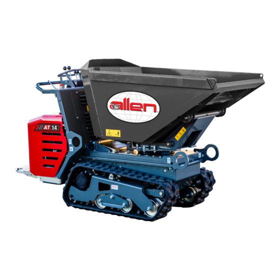
allen AT14S Operations & Parts Manual
Track buggy
Hide thumbs
Also See for AT14S:
- Operations & parts manual (124 pages) ,
- Operations & parts manual (68 pages)

Subscribe to Our Youtube Channel
Related Manuals for allen AT14S


Summary of Contents for allen AT14S
- Page 1 AT14S & AT12L TRACK BUGGY OPERATIONS & PARTS MANUAL MANUAL PART #: 065300 | REVISION: C...
- Page 2 For your own safety and protection from personal injury, carefully read, understand, and observe the safety instructions described in this manual. Keep this manual or a copy of it with the machine at all times.
- Page 3 Allen Engineering Corporation (AEC). AEC assumes no responsibility or liability for any errors or inaccuracies that may appear in this manual.
-
Page 4: Limited Warranty
Allen reserves the choice to repair or replace. 2. If Allen chooses to replace the part, it will be at no cost to the customer and will be made available to the Allen Distributor, Dealer, or Rental Center from whom the End User purchased the product. -
Page 5: Table Of Contents
Table of Contents Title Page Limited Warranty Table of Contents Information Contained In This Manual Dealer Information Ordering Parts Model Number - Serial Number Codes Unit Identification Technical specifications Dimensions Engine Specifications Engine Serial Number Information Section 1 - Safety State Regulations Federal Regulations Safety Information... - Page 6 Table of Contents - Continued Title Page Parts Framework Assembly Hydraulic Tank Assembly Engine Assembly Hydraulic Pump Assembly Hydraulic Cooler Assembly Fuel Tank Assembly Wiring Assembly Operator Console Assembly Throttle Assembly Control Lever Assembly Block Drainages and Servos Hood Assembly Bucket Valve Fitting Assembly Hydraulic Hose Assembly Decals...
-
Page 7: Information Contained In This Manual
Complete any warranty requirements as specified by the engine manufacturer in their instructions found inside the manual box located on the operator’s control panel. Your engine is not manufactured by Allen Engineering Corporation, Inc, and therefore is not covered under Allen Engineering Corporation, Inc warranty. -
Page 8: Dealer Information
Dealer Information Your Dealer has Allen Engineering Corporation trained mechanics and original Allen replacement parts. Always contact the Allen Dealer who sold you this machine for Allen Certified repairs and replacement parts. Place Allen Dealer information below for future reference. -
Page 9: Ordering Parts
Ordering Parts Section 4 contains illustrated parts lists for help in ordering replacement parts for your machine. Fol- low the instructions below when ordering parts to insure prompt and accurate delivery: All orders for service parts - include the serial number for the machine. Shipment will be delayed if this information is not available. -
Page 10: Model Number - Serial Number Codes
Model Number - Serial Number Codes Manufacturer’s Codes: When ordering parts or requesting service information, you will always be asked to specify the model and serial numbers of the machine. The legends below specifically defines each significant character or group of characters of the Model Number and Serial Number codes. Model Number AT14 S Series... -
Page 11: Unit Identification
Unit Identification Unit Identification Plate Location: An identification plate listing the model number and the serial number is attached to each unit and is located on the lower inside face of the console. See image below for serial number plate location. This plate should not be removed at any time. -
Page 12: Technical Specifications
Technical Specifications Operating weight (without operator) 1,753 1000 Operating capacity 2,205 0.58 Load capacity: - heaped (SAE Standard) 20.4 0.48 - flat: sand 16.9 liquid 14.1 ENGINE Petrol Engine HONDA GX630 Maximum engine rotation speed 3600 Max. power at maximum speed HP/Kw 20.8 / 15.5 Displacement... -
Page 13: Dimensions
Dimensional Specifications 31.1” 7.08” 34.6” 2211 18.6” 31.1” 87.0” Page 13 065300 - 09/2016... -
Page 14: Engine Specifications
Engine Specifications Engine Type Air-cooled 4-stroke OHV Bore x Stroke 78 X 72 mm Displacement 688 cm3 Net Power Output* 20.8 hp (15.5 kW) @ 3,600 rpm 35.6 lbs ft (48.3 Nm) @ 2,500 rpm Net Torque Counterclockwise (from PTO shaft PTO Shaft Rotation side) Compression Ratio... -
Page 15: Engine Serial Number Information
Engine Serial Number Information Record the engine serial number, type and purchase date in the spaces below. You will need this information when ordering parts and when making technical and warranty inquiries. Page 15 065300 - 09/2016... -
Page 16: Section 1 - Safety
State Regulations SECTION 1 Proposition 65 Warning SAFETY Page 16 065300 - 09/2016... -
Page 17: Federal Regulations
Federal Regulations SECTION 1 Respiratory Hazards SAFETY Page 17 065300 - 09/2016... -
Page 18: Safety Information
Safety Information SECTION 1 SAFETY Do not operate or service the equipment before reading the entire manual. Safety precautions should be followed at all times when operating this equipment. Failure to read and understand the safety mes- sages and operating instructions could result in injury to yourself and others. SAFETY NOTES The four safety notes shown below will inform you about potential hazards that could injure you or oth- ers. - Page 19 Safety Symbols SECTION 1 SAFETY Potential hazards associated with the operation of this equipment will be referenced with hazard symbols which may appear throughout this manual in conjunction with safety notes. Page 19 065300 - 09/2016...
-
Page 20: General Safety
For more information contact an Authorized Service Center. Allen Engineering Corporation reserves the right to make changes without prior notification. Everything in this manual belongs to the AEC, therefore no part or diagram can be used for any other use without authorization. - Page 21 General Safety (cont’d) SECTION 1 SAFETY • Do not spill hydraulic or lubricating oil or any other liquid on the ground during maintenance; pick it up and dispose of it at authorized companies. • Unauthorized personnel must be prohibited from operating the vehicle by removing the ignition key. The person it is handed over to is responsible for any harm and damage caused to third parties.
- Page 22 General Safety (cont’d) SECTION 1 SAFETY The present manual contains the information required to run the machine. Contact the Manufacturer for any spare parts, accessories or information you might require. The tracked buggy fit with bucket or open dump body serves to carry and dump materials. The materials being handled must comply with the characteristics of the equipment currently being used.
- Page 23 General Safety (cont’d) SECTION 1 SAFETY • If the loading bucket is also equipped with a shovel, it must be positioned as high as possible, to pre- vent it from interfering with the remaining structure when tipping over. • If a transporter equipped with AV or AVP systems is used (high unloading system, variable, with or without loading shovel) the following additional recommendations must be respected: •...
- Page 24 General Safety (cont’d) SECTION 1 SAFETY UPHILL OR DOWNHILL - EMPTY 30° MAX 25° MAX FLAT GROUND - EMPTY UPHILL OR DOWNHILL, EMPTY AND LOADED MAX 22 % Page 24 065300 - 09/2016...
- Page 25 General Safety (cont’d) SECTION 1 SAFETY USING THE OPERATOR PLATFORM: • The PLATFORM must be LIFTED (max. height) with the OPERATOR on the GROUND. • The PLATFORM must be LOWERED with the OPERATOR ON IT. • Under no circumstances is the operator to drive while the platform is lowered. Page 25 065300 - 09/2016...
-
Page 26: Transportation And Lifting Safety
Lifting and Transportation Safety SECTION 1 SAFETY Kg 630 / 770 The vehicle must only be lifted when empty and it is of utmost importance to strictly comply with the following: • Lower the load bucket slightly to release the two hooks located on the sides of the dump body: the other two are positioned on the sides of the driving position (see figure). - Page 27 Lifting and Transportation Safety (cont’d) SECTION 1 SAFETY • Use cables or chains rated for the weight to be lifted: when empty and fit with bucket, the ma- chine weights approximately 630 Kg. The machine fitted with high tip skip weights approximately 770 •...
-
Page 28: Safety Retainer Positioning
Safety Retainer Positioning SECTION 1 SAFETY Position A Position B To insert the safety lock make the following operations: disconnect the split pin ”1”; unthread the pivot “2”; rotate the safety lock “3” till enveloping the liner of the lifting cylinder of the body (see “Position B”);... -
Page 29: Section 2 - Operations
Driving Position Controls SECTION 2 OPERATIONS 1 – RIGHT TRACK DRIVE CONTROL LEVER 2 – LEFT TRACK DRIVE CONTROL LEVER 3 – LOAD BUCKET UP-DOWN LEVER 4 – SELF-LOADING BUCKET LEVER / LOADING BUCKET ROTATION LEVER 5 – DRIVING LEVER FOR THE LIFTING OF THE UNLOADING SKIP 6 –... -
Page 30: General Operating Instructions
General Operating Instructions SECTION 2 OPERATIONS The vehicle drive is activated via levers “1” and “2”. Hereunder are the detailed descriptions of the manoeuvres that are to be performed to drive forward, backward and to steer. FORWARD GEAR: bring levers “1” and “2” simultaneously forward. REVERSE GEAR: bring levers “1”... - Page 31 General Operating Instructions (cont’d) SECTION 2 OPERATIONS STEERING FORWARD TO THE RIGHT: WITH THE VEHICLE STOPPED: bring lever “2” forward with respect to lever “1” WHILE THE VEHICLE IS MOVING: reverse lever “1” with respect to lever “2” STEERING BACKWARDS TO THE RIGHT: WITH THE VEHICLE STOPPED: bring lever “2”...
-
Page 32: General Operations
General Operations SECTION 2 OPERATIONS VEHICLE USE In order to safeguard the integrity and functionality of the track, please follow the recommendations and specifications below: • Avoid sudden turns and changes in direction while driving on the road, especially on rough and hard ground, bumpy and sharp ground or with high friction. - Page 33 General Operations (cont’d) SECTION 2 OPERATIONS ATTENTION!!! The anomalies listed above require the damaged track to be replaced immediately. ABRASIONS OR TEARS DUE TO FATIGUE OR EXTERNAL FACTORS • Generally, these problems are caused by the way the vehicle is used or the environment in which the work is carried out.
-
Page 34: Section 3 - Service
General Maintenance SECTION 3 SERVICE GREASE POINTS Periodically grease the indicated points. The lubrication intervals and the lubricant that is to be used are indicated in the table of lubricants below. It is recommended to keep all the grease fittings clean and efficient and replace them if inefficient or damaged. - Page 35 General Maintenance (cont’d) SECTION 3 SERVICE 50 h Page 35 065300 - 09/2016...
- Page 36 General Maintenance (cont’d) SECTION 3 SERVICE Grease the rotation slewing ring through the 2 greasing points “D” and “E”, making sure to apply more grease to the front left point “E”. Page 36 065300 - 09/2016...
- Page 37 General Maintenance (cont’d) SECTION 3 SERVICE 1 – HYDRAULIC OIL TANK FILLER CAP 2 – FUEL FILLER CAP 3 – TRACK TENSIONING DEVICE 4 – HYDRAULIC OIL INTAKE FILTER 5 – DISCHARGE HYDRAULIC OIL FILTER 6 – AIR FILTER Page 37 065300 - 09/2016...
- Page 38 General Maintenance (cont’d) SECTION 3 SERVICE 1 – HYDRAULIC OIL TANK FILLER CAP Complete change lt. 18.0 Use 46 Weight Hydraulic Oil. Replace the oil after the first 200 HOURS of operation and every 1000 HOURS thereafter or once a year. To fill or top up, check that the oil is between the min.
-
Page 39: Track Tightening
General Maintenance (cont’d) SECTION 3 SERVICE 3 – TRACK TENSIONING DEVICE This device is used to restore correct track tightness if they loosen during use. TIGHTENING THE TRACKS With use, the tracks tend to loosen. When operating with loose tracks, they tend to slip over the driving wheel teeth causing it to jump its housing or to work in precarious fashion, damaging and causing wear to the housing. -
Page 40: Hydraulic Oil Intake Filter
General Maintenance (cont’d) SECTION 3 SERVICE REPLACING THE HYDRAULIC OIL INTAKE FILTER The filter is located inside the hydraulic oil tank (see picture). Replace the filter after the first 50 HOURS of operation and every 500 HOURS thereafter. Remove the oil tank cover by loosing the screws “A”, unscrew the filter “F”... -
Page 41: Air Filter
General Maintenance (cont’d) SECTION 3 SERVICE REPLACING THE AIR FILTER The air filter “F” is located under the engine bonnet. To clean the cartridge, it is sufficient to remove the top cover, remove the cartridge and clean with com- pressed air. Do not use solvents, brushes or rags to prevent damage to the cartridge. The air filter should be replaced with another one having the same characteristics. -
Page 42: Wheel Gear Maintenance
General Maintenance (cont’d) SECTION 3 SERVICE WHEEL GEARS Each track is driven by a reducer, coupled to a hydrostatic motor, fitted with an internal brake with negative-type of multiple discs. The brake is activated by the hydrostatic system by means of the trans- mission levers (forward - reverse). - Page 43 General Maintenance (cont’d) SECTION 3 SERVICE CAP POSITION FOR FILLING CAP POSITION FOR VERIFICATION LEVEL CAP POSITION FOR VERIFICATION LEVEL CAP POSITION FOR EMPTYING Therefore, this section does not require particular maintenance. If the oil level in the reducer should decrease or increase when there are no external leaks, the internal seals of the reducer itself must be checked by an authorized service center.
-
Page 44: Maintenance Schedule
Maintenance Chart SECTION 3 SERVICE HOURS FOR FIRST REPLACEMENT OPERATION COMPONENT INVOLVED ● Oil intake filter cartridge ● Discharge oil filter cartridge REPLACE ● Air filter cartridge ● Hydraulic oil FREQUENCY OF SUBSEQUENT REPLACEMENTS (in hours) OPERATION COMPONENT INVOLVED 100 200 500 1000 ●... -
Page 45: Hydrostatic Transmission System
General Maintenance (cont’d) SECTION 3 SERVICE HYDROSTATIC TRANSMISSION SYSTEM 1. RIGHT TRACK HYDRAULIC PUMP 2. LEFT TRACK HYDRAULIC PUMP 3. DRIVE GEARMOTOR 4. DISCHARGE OIL FILTER 5. HYDRAULIC OIL TANK AND OIL INTAKE FILTER 6. SERVICE HYDRAULIC PUMP 7. WATER/OIL COOLER Page 45 065300 - 09/2016... -
Page 46: Pump Maintenance
General Maintenance (cont’d) SECTION 3 SERVICE PUMPS MAINTENANCE In order to service the pump and the hydraulic valve once the body is tipped and safely blocked, loose the screw “U” and “V” and then remove the protection carters After finished the necessary maintenance, locate again the panels and tie the screws. ADJUSTMENT AND ZERO SETTING OF THE HYDRAULIC PUMPS The track control levers on the control panel automatically return to zero (neutral position), inde- pendently of the revolutions of the engine. - Page 47 General Maintenance (cont’d) SECTION 3 SERVICE To adjust the pumps and obtain zero setting, proceed in the following order: • Position the machine on a flat horizontal surface; • Unscrew the axle bolt on the control cable from the regulating poles “A”, “C” or both; •...
-
Page 48: Transmission Pressures
General Maintenance (cont’d) SECTION 3 SERVICE CHECK MAX. PRESSURE OF HYDROSTATIC TRANSMISSION SYSTEM Page 48 065300 - 09/2016... - Page 49 General Maintenance (cont’d) SECTION 3 SERVICE • With the vehicle stationary and the engine off, connect no.4 400 bar full scale gauges to points “1”, “2”, “3” and “4”, start the endothermic engine and bring it to the max. power allowed (3200 rpm for the petrol engine and 3600 rpm for the diesel engine).
-
Page 50: Hydraulic System Service Pressures
General Maintenance (cont’d) SECTION 3 SERVICE CHECK MAX. PRESSURE OF THE HYDRAULIC SYSTEM SERVICE PRESSURES The operation consists of detecting the main valve maximum pressure. Verify by following the instruc- tions below: With the vehicle stationary and the engine off, connect a 250 bar full-scale gauge to position “6” •... -
Page 51: Electrical System
General Maintenance (cont’d) SECTION 3 SERVICE ELECTRICAL SYSTEM Battery “B” is found under the bonnet, on the left side. BATTERY SPECIFICATIONS: VOLTAGE: 12 V CONSUMPTION: 55 Ah DISCHARGE: 450 A A - IGNITION KEY B - BATTERY The key in switch “A” is only removed when this is disconnected (“OFF” position). ATTENTION! Verify the level of the battery liquid every 100 HOURS. - Page 52 General Maintenance (cont’d) SECTION 3 SERVICE Keep the cable terminals fastened well and protected with grease or even better with pure Vaseline. When disconnecting the battery, the earth wire (-) must be disconnected first. When connecting the battery, the positive wire (+) must be connected first. Keep metal tools and objects away from the battery poles as these may short-circuit the terminals and pose a risk of burns.
-
Page 53: Troubleshooting
Troubleshooting SECTION 3 SERVICE PROBLEM CAUSE No oil in the tank Check the level and top-up, if necessary Air in the hydraulic drive system Verify the efficiency of the pipes and fittings The vehicle jerks Clogged hydrost. oil filter Replace the filter cartridge Control levers operated too abruptly and Operate the lever gently quickly... -
Page 54: Framework Assembly
Frame Assembly SECTION 4 Illustration PARTS Page 54 065300 - 09/2016... - Page 55 Frame Assembly SECTION 4 Parts List PARTS Item Part # Description 55141569 FRAME 33591805 BUSHING 30060578 PLATE 30060575 RIGHT MOUNTING 03366300 03240701 FSTN, SCREW M10X40 8.8 03730003 SPRING 30060568 OPERATOR’S FOOTBOARD 03366300 NUT, M10 03731430 SPRING 45020435 SPACER 03386201 FSTN, WASHER 10,5x21x2 03241600 FSTN, SCREW M10x90 8.8 068666...
-
Page 56: Hydraulic Tank Assembly
Hydraulic Tank Assembly SECTION 4 Illustration PARTS Page 56 065300 - 09/2016... - Page 57 Hydraulic Tank Assembly SECTION 4 Parts List PARTS Item Part # Description Qty. 15101373 OIL TANK 03160006 WASHER 13166000 PLUG 13153900 JUNCTION 15101265 COVERING 03491002 O.R. RING 13572402 COLLAR 13150036 REDUCTION 03160901 WASHER 03383000 WASHER 065259 FILTER 98080003 OIL TANK KIT 98080004 KIT COLLAR 98080005...
-
Page 58: Engine Assembly
Engine Assembly SECTION 4 Illustration PARTS Page 58 065300 - 09/2016... - Page 59 Engine Assembly SECTION 4 Parts List PARTS Item Part # Description Qty. 13001022 ENGINE 30014951 CONVEYOR 20051926 MOTOR BASE 03231111 FSTN, SCREW M8x50 8.8 03385201 WASHER 20051903 CLAMP 03230601 CLAMP 03385401 WASHER 03365101 FSTN, NUT M8 20051904 CLAMP 20051905 CLAMP 03009696 MUFFLER 065587...
-
Page 60: Hydraulic Pump Assembly
Hydraulic Pump Assembly SECTION 4 Illustration PARTS Page 60 065300 - 09/2016... - Page 61 Hydraulic Pump Assembly SECTION 4 Parts List PARTS Item Part # Description Qty. 065262 PUMP 25150273 CONTROL DEVICE 25150285 ADJUSTER 03235280 FSTN, SCREW M8x80 8.8 13154200 CONNECTOR 13843001 VALVE 13153900 CONNECTOR 03160006 WASHER 03150303 CONNECTOR 03160902 WASHER 03150600 SCREW 03635007 CONNECTOR 065589 CHECKING COUPLING...
-
Page 62: Hydraulic Cooler Assembly
Hydraulic Cooler Assembly SECTION 4 Illustration PARTS Page 62 065300 - 09/2016... - Page 63 Hydraulic Cooler Assembly SECTION 4 Parts List PARTS Item Part # Description Qty. 33840908 RADIATOR 45155465 SUPPORT 03220701 FSTN, SCREW M6x25 8.8 03383000 WASHER, 6,1x11,1x1,6 03383311 WASHER, 6,6x18x2 03220601 FSTN SCREW M6x20 8.8 13152900 JUNCTION 03606000 ELBOW 03160006 WASHER 03628100 CONNECTOR 03639800 JUNCTION...
-
Page 64: Fuel Tank Assembly
Fuel Tank Assembly SECTION 4 Illustration PARTS Page 64 065300 - 09/2016... - Page 65 Fuel Tank Assembly SECTION 4 Parts List PARTS Item Part # Description Qty. 15101393 FUEL TANK 065593 PLUG 15101405 PANEL 03480021 FAIRLEAD 30322212 PANEL 13009605 CARBON CANISTER 13572444 COLLAR 03383311 WASHER 03383000 WASHER, 6,1x11,1x1,6 03220200 FSTN, SCREW M6x12 8.8 15101425 PLATE 03365100 FSTN, NUT M8...
-
Page 66: Wiring Assembly
Wiring Assembly SECTION 4 Illustration PARTS Page 66 065300 - 09/2016... - Page 67 Wiring Assembly SECTION 4 Parts List PARTS Item Part # Description Qty. 03010017 BATTERY 30013521 PROTECTION 45500258 CLAMP 60031668 NEGATIVE POLE CABLE 60031669 POSITIVE POLE CABLE 60020116 FLANGE 065264 BATTERY DISCONNECTING DEVICE 60031667 NEGATIVE POLE CABLE 03480601 LAMP 60031757 CABLE 33482061 WARNING LIGHT 03220602...
-
Page 68: Operator Console Assembly
Operator Console Assembly SECTION 4 Illustration PARTS Page 68 065300 - 09/2016... - Page 69 Operator Console Assembly SECTION 4 Parts List PARTS Item Part # Description Qty. 55030821 FRAME - DRIVING PLACE 13480010 PLUG 065266 PROTECTION 30014950 PROTECTION 03383311 WASHER, 6,6x18x2 03227702 FSTN, SCREW M6x20 4.6 03240501 FSTN, SCREW M10x30 8.8 03386011 WASHER, 11x30x2,5 03366300 FSTN, NUT M10 30014864...
-
Page 70: Throttle Assembly
Throttle Assembly SECTION 4 Illustration PARTS Page 70 065300 - 09/2016... - Page 71 Throttle Assembly SECTION 4 Parts List PARTS Item Part # Description Qty. 065267 HAND-LEVER 03227520 FSTN, SCREW M6x25 10.9 03383311 WASHER, 6,6x18x2 068667 FSTN, NUT M6 13430001 FORK 13439570 065268 CABLE 03220901 FSTN, SCREW M6x35 8.8 03364001 FSTN, NUT M6 (5588) 065266 PROTECTION 98080007...
-
Page 72: Control Lever Assembly
Control Lever Assembly SECTION 4 Illustration PARTS Page 72 065300 - 09/2016... - Page 73 Control Lever Assembly SECTION 4 Parts List PARTS Item Part # Description Qty. 065574 COMPLETE LEVER, SX TRANSMISSION 03581202 HANDGRIP 33592601 BUSH 03386201 WASHER, 10,5x21x2 03366300 FSTN, NUT M10 03241700 FSTN, SCREW M10x100 8.8 065575 COMPLETE LEVER, DX TRANSMISSION 068667 FSTN, NUT M6 03383000 WASHER, 6,1x11,1x1,6...
- Page 74 Control Lever Assembly SECTION 4 Illustration PARTS Page 74 065300 - 09/2016...
- Page 75 Control Lever Assembly SECTION 4 Parts List PARTS Item Part # Description Qty. 065581 03168500 GASKET 13150036 CONNECTOR 13161234 CONNECTOR 03600009 ELBOW 03630302 JUNCTION 03381000 WASHER, 5,3x10x1 03214600 FSTN, SCREW M5x45 8.8 03363001 FSTN, NUT M5 63840000 LEVER 98080015 KIT LEVER Page 75 065300 - 09/2016...
-
Page 76: Block Drainages And Servos
Block Drainages and Servos SECTION 4 Illustration PARTS Page 76 065300 - 09/2016... - Page 77 Block Drainages and Servos SECTION 4 Parts List PARTS Item Part # Description Qty. 25200650 CONNECTOR 03160901 WASHER 13150036 CONNECTOR 13166010 PLUG 03150006 SCREW 45500134 SUPPORT 03383202 WASHER, 6,4x12,5x1,6 03220901 FSTN, SCREW M6x35 068667 FSTN, NUT M6 03220401 FSTN, SCREW M6x16 8.8 03600009 ELBOW 065582...
-
Page 78: Hood Assembly
Hood Assembly SECTION 4 Illustration PARTS Page 78 065300 - 09/2016... - Page 79 Hood Assembly SECTION 4 Parts List PARTS Item Part # Description Qty. 30014900 HOOD 03709010 ADHESIVE 065331 ISOLATION 065332 PANEL 065583 VIBRATION-DAMPING 03364001 FSTN, NUT M6 065269 LOCKING 03220601 FSTN, SCREW M6x20 8.8 068666 WASHER, 6,4x12,5x1,6 03383311 WASHER, 6,6x18x2 068667 FSTN, NUT M6 065335 GASKET...
-
Page 80: Bucket Valve Fitting Assembly
Bucket Valve Fitting Assembly SECTION 4 Illustration PARTS Page 80 065300 - 09/2016... - Page 81 Bucket Valve Fitting Assembly SECTION 4 Parts List PARTS Item Part # Description Qty. 065624 DISTRIBUTOR 13160013 PLUG 03160902 WASHER 03160901 WASHER 065270 KIT SEALS 13152800 JUNCTION 03385401 WASHER 03231301 FSTN, SCREW M8x60 8.8 03385201 WASHER, 8,4x17x1,6 03365100 FSTN, NUT M8 25200603 CONNECTOR 065589...
-
Page 82: Hydraulic Hose Assembly
Hydraulic Hose Assembly SECTION 4 Illustration PARTS Page 82 065300 - 09/2016... - Page 83 Hydraulic Hose Assembly SECTION 4 Parts List PARTS Item Part # Description Qty. 03122034 HOSE, 59" 3/16DIA FEMALE 1/4" BSPP- FEMALE 1/8" BSPP 03122031 HOSE, 39.3" 3/16DIA FEMALE 1/4" BSPP- FEMALE 1/8" BSPP 03111933 HOSE, 17.7" 3/16DIA FEMALE 3/8" - FEMALE 3/8" 90° BSPP 03121890 HOSE, 51.1"...
- Page 84 Decal Assembly SECTION 4 Illustration PARTS Page 84 065300 - 09/2016...
-
Page 85: Decals
Decal Assembly SECTION 4 Parts List PARTS Item Part # Description Qty. 03666063 DECAL, ADJUSTING VOLTAGE TRACK 03660099 DECAL, DANGER OF SHEARING 03660098 DECAL, DWELL IN ACTION 03660252 DECAL, STARTER 03665029 DECAL, LPA 88 03660177 DECAL, UNLEADED GASOLINE 03660230 DECAL, GASOLINE 03665022 DECAL, LWA 101 03660170... - Page 86 Decal Assembly SECTION 4 Illustration (cont’d) PARTS Page 86 065300 - 09/2016...
- Page 87 Decal Assembly SECTION 4 Parts List (cont’d) PARTS Item Part # Description Qty. 03660062 DECAL, ENTERING FIXED POINT 03660099 DECAL, DANGER OF SHEARING 03660098 DECAL, DWELL IN ACTION 03666066 DECAL, HYDRAULIC Page 87 065300 - 09/2016...
-
Page 88: Maintenance Tools
Maintenance Tools SECTION 4 Illustration PARTS Page 88 065300 - 09/2016... - Page 89 Maintenance Tools SECTION 4 Parts List PARTS Item Part # Description Qty. 03679700 HOLDER 03519600 GREASING PUMP 03519800 PIPE 03519900 HEAD 03572000 SCREWDRIVER 03572300 NIPPER 03570000 KEY 10-13 mm 83130493 99100033 03679000 HOLDER 065300 PARTS CATALOG 03570403 Page 89 065300 - 09/2016...
-
Page 90: Hourmeter
Hourmeter SECTION 4 Illustration PARTS Page 90 065300 - 09/2016... - Page 91 Hourmeter SECTION 4 Parts List PARTS Item Part # Description Qty. 065625 HOURMETER Page 91 065300 - 09/2016...
-
Page 92: Bucket Hydraulic Cylinder Assembly
Bucket Hydraulic Cylinder Assembly SECTION 4 Illustration PARTS Page 92 065300 - 09/2016... - Page 93 Bucket Hydraulic Cylinder Assembly SECTION 4 Parts List PARTS Item Part # Description Qty. 03112148 HOSE, 106.2” 1/4DIA OCCH - FEMALE 1/4” BSPP 03160901 WASHER 03150006 SCREW 03581403 BALL 065266 PROTECTION 03220902 FSTN, SCREW M6x40 8.8 13572414 COLLAR 065637 LEVER Page 93 065300 - 09/2016...
-
Page 94: Swivel Hydraulic Cylinder Assembly
Swivel Hydraulic Cylinder Assembly SECTION 4 Illustration PARTS Page 94 065300 - 09/2016... - Page 95 Swivel Hydraulic Cylinder Assembly SECTION 4 Parts List PARTS Item Part # Description Qty. 03121440 HOSE, 82.6” 1/4DIA FEMALE 1/4” - FEMALE 1/4” 90° BSPP 03160901 WASHER 13150032 JUNCTION 065635 LEVER 03581203 HANDGRIP 03160902 WASHER 065636 VALVE 13153950 JUNCTION 03150600 SCREW 25160560 HOSE, RIGID FROM CYLINDER VALVE...
-
Page 96: Trilateral Tipping Bucket Assembly
Trilateral Tipping Bucket Assembly SECTION 4 Illustration PARTS Page 96 065300 - 09/2016... - Page 97 Trilateral Tipping Bucket Assembly SECTION 4 Parts List PARTS Item Part # Description Qty. 068670 BUCKET 55020770 EVOLUTION FRAME 03241000 FSTN, SCREW M10x55 10.9 03366001 FSTN, NUT M10 065271 PINION 45030115 BEARING DISK 03386300 WASHER, 10,5x28x4 065626 03429700 STOP RING 062437 PIN 400L 068658...
- Page 98 Trilateral Tipping Bucket Assembly SECTION 4 Illustration (cont’d) PARTS Page 98 065300 - 09/2016...
- Page 99 Trilateral Tipping Bucket Assembly SECTION 4 Parts List (cont’d) PARTS Item Part # Description Qty. 10013194 STEADY FRAME 065631 30014830 CRANKCASE 30014831 CRANKCASE 55081584 PLATE 55081657 PLATE 45155438 SUPPORT 45155439 PLATE 45300076 GUIDE BLOCK 03245101 FSTN, SCREW M10x40 8.8 03366001 FSTN, NUT M10 065632 03364004...
- Page 100 Trilateral Tipping Bucket Assembly SECTION 4 Illustration (cont’d) PARTS Page 100 065300 - 09/2016...
- Page 101 Trilateral Tipping Bucket Assembly SECTION 4 Parts List (cont’d) PARTS Item Part # Description Qty. 10013152 SUPPORT 13480217 PLUG 03400602 03231501 FSTN, SCREW M8x70 8.8 03572040 WASHER, 8.4x16.6x2.29 10013151 CRANKCASE 03220401 FSTN, SCREW M6x16 8.8 068666 WASHER, 6,4x12,5x1,6 Page 101 065300 - 09/2016...
-
Page 102: Hydraulic Tank Connections
Hydraulic Tank Connections SECTION 4 Illustration PARTS Page 102 065300 - 09/2016... - Page 103 Hydraulic Tank Connections SECTION 4 Parts List PARTS ITEM PART NO. DESCRIPTION 25250480 CYLINDER 065639 KIT- SEALS 45070934 03221000 SCREW 068667 065640 99150014 LATCH 03739800 SPLIT PIN 03112033 PIPE 03168500 GASKET 03150006 SCREW Page 103 065300 - 09/2016...
-
Page 104: At12L Control Plate
Control Plates SECTION 4 Illustration PARTS Page 104 065300 - 09/2016... - Page 105 Control Plates SECTION 4 Parts List PARTS ITEM PART NO. DESCRIPTION 03666251 PLATE 03666253 PLATE Page 105 065300 - 09/2016...
-
Page 106: At12L Control Levers
Control Levers SECTION 4 Illustration PARTS Page 106 065300 - 09/2016... - Page 107 Control Levers SECTION 4 Parts List PARTS ITEM PART NO. DESCRIPTION 25300372 DISTRIBUTOR 065270 KIT SEALS 03168500 GASKET 13166010 PLUG 13152700 CONNECTOR 03605800 ELBOW 23150232 LEVER 065635 LEVER 03366001 065266 PROTECTION 03581203 HANDGRIP Page 107 065300 - 09/2016...
-
Page 108: At12L Manufacturer Plates
Manufacturer Plates SECTION 4 Illustration PARTS Page 108 065300 - 09/2016... - Page 109 Manufacturer Plates SECTION 4 Parts List PARTS ITEM PART NO. DESCRIPTION 03660062 PLATE 03660113 MANUFACTURER’S PLATE 03660123 MANUFACTURER’S PLATE 03666024 PLATE 03660098 PLATE 03664875 MANUFACTURER’S PLATE 13480602 PLUG Page 109 065300 - 09/2016...
-
Page 110: At12L Bucket Assembly
AT12L Bucket Assembly SECTION 4 PARTS Illustration Page 110 065300 - 09/2016... - Page 111 AT12L Bucket Assembly SECTION 4 Parts List PARTS ITEM PART NO. DESCRIPTION 065643 10012360 SKIP FOR EARTH AND CONCRETE 03366300 03221000 SCREW 068667 065628 VIBRATION-DAMPING 91470151 WASHER 30322086 GASKET 23160015 RABBET 03220401 SCREW 03383000 WASHER 03383311 WASHER 065645 03735002 SPRING 065646 COUPLING 03433400...
-
Page 112: At12L Bucket Plate
Bucket Plate SECTION 4 Illustration PARTS Page 112 065300 - 09/2016... - Page 113 Bucket Plate SECTION 4 Parts List PARTS ITEM PART NO. DESCRIPTION 03660099 PLATE Page 113 065300 - 09/2016...
-
Page 114: At12L Bucket Chassis
AT12L Bucket Chassis SECTION 4 Illustration PARTS Page 114 065300 - 09/2016... - Page 115 AT12L bucket Chassis SECTION 4 Parts List PARTS ITEM PART NO. DESCRIPTION 68646 LIFTING CHASSIS 68647 LIFTING CHASSIS 68647 BUSH 065647 068649 LUBRICATOR 068650 BEARING RING 068651 WASHER 068652 068653 SKIP 068654 SCREW 068655 WASHER 068656 Page 115 065300 - 09/2016...
-
Page 116: At12L Hydraulic Tank Connections
AT12L Hydraulic Tank Connections SECTION 4 Illustration PARTS Page 116 065300 - 09/2016... - Page 117 AT12L Hydraulic Tank Connections SECTION 4 Parts List PARTS ITEM PART NO. DESCRIPTION 065642 CYLINDER 065641 KIT- SEALS 45020147 SPACER 03272200 SCREW 03388910 WASHER 03369110 45070939 03391000 WASHER 03391050 WASHER 03371110 25200548 JUNCTION 03385201 WASHER 03365100 03122000 PIPE 03150006 SCREW 03168500 GASKET 03605800...
-
Page 118: Filter Kit
Filter Kit SECTION 4 PARTS Item Part # Description Qty. 066444 KIT, AT14 BUGGY FILTER 066589 FILTER, AT14 BUGGY AIR (4508302) 057994 OIL FILTER CH-1000 40KOLR 5205002-S1 066434 FILTER, HYDRO DISCHARGE F/ AT14 057993 FUEL FILTER CH-1000 40KHR 2405013-S1 066433 FILTER, CARBON CANISTER F/ AT14 Page 118 065300 - 09/2016... - Page 119 SECTION 4 Notes PARTS Page 119 065300 - 09/2016...
-
Page 120: Hydraulic Schematic
Hydraulic Schematic Page 120 065300 - 09/2016... - Page 121 Hydraulic Schematic (cont’d) Page 121 065300 - 09/2016...
-
Page 122: Electrical Schematic
Electrical Schematic Page 122 065300 - 09/2016... - Page 123 Manual Revision MANUAL REVISION DETAIL REVISION # REVISION DATE REVISION REFERENCE # REVISION BY 09/2016 Initial Release 07/2017 18-002, 18-027, 18-030, 18-031, 18-036 05/2018 MN 18-036...
- Page 124 P.O. BOX 819 PARAGOULD, AR 72451 USA 800.643.0095 (USA ONLY) / 870.236.7751 FAX: 800.643.0097 (USA ONLY) / 870.236.3934 WWW.ALLENENG.COM CONNECT WITH US ON...
Need help?
Do you have a question about the AT14S and is the answer not in the manual?
Questions and answers