Table of Contents
Advertisement
Quick Links
Advertisement
Table of Contents

Related Manuals for Dell PowerEdge FN 410S


Summary of Contents for Dell PowerEdge FN 410S
- Page 1 Dell PowerEdge FN 410S I/O Aggregator Getting Started Guide...
- Page 2 WARNING: A WARNING indicates a potential for property damage, personal injury, or death. Copyright © 2014 Dell Inc. All rights reserved. This product is protected by U.S. and international copyright and intellectual property laws. Dell ™...
-
Page 3: Table Of Contents
Unpacking the Aggregator ..........................13 Unpacking Steps 5 Installing and Configuring the Aggregator............15 .............. 16 Installing a switch in a Dell PowerEdge FX2 Server Chassis ......................16 Connecting a Console Terminal .................... 17 Invoking the X-Loader and U-Boot CLIs ......................17 Reconfiguring Default Settings .......................... - Page 4 7 Programmable-MUX Mode.................. 25 ............25 Configuring and Bringing Up the Programmable-MUX Mode 8 Next Steps.........................27 9 Technical Specifications..................29...
-
Page 5: About This Guide
About this Guide This document helps you in getting started with Dell PowerEdge FN 410S I/O Aggregator. For complete installation and configuration information, refer to the documents listed below: Table 1. Dell PowerEdge FN 410S I/O Aggregator Documents Information Documentation... -
Page 7: Introduction
FX2 server chassis Installation Guide . For information about how to configure and monitor switch features, refer to the Configuration Guide for the Dell PowerEdge FN 410S I/O Aggregator, which is available on the Dell Support website at http:// www.dell.com/support/manuals. -
Page 9: Hardware Overview
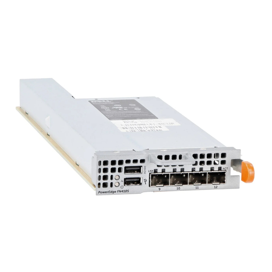
Figure 1. I/O Aggregator Front Panel Port Numbering When installed in a server enclosure, the Dell PowerEdge FN 410S I/O Aggregator ports are numbered from 1 to 12. Ports from 1 to 8 are internal server-facing ports. Ports from 9 to 12 are external ports numbered from left to right on the switch. -
Page 10: System Status
from a console terminal connected to the port through the provided serial cable (with USB UART-A to back-plane to CMC). The console port supports asynchronous data of eight data bits, one stop bit, no parity bit, and no flow control. The default baud rate is 115200 bps. The lower USB port (in the following figure) functions as an external flash drive that you can use to store configuration files, load new images, and import or export scripts or report files used in virtualization application. - Page 11 NOTE: When the ingress air temperature exceeds 60°C, the Status LED turns Amber and a major alarm is triggered. Table 3. SFP+ Port LEDs Port LED LED Color/Display Description Link LED The port is down. Solid green The port is up and can transmit traffic at maximum speed.
-
Page 13: Installation
Installation This switch installation procedure assume the Dell PowerEdge FX2 server chassis is installed correctly. For complete instructions for installation, refer to the Dell PowerEdge FX2 server chassis Installation Guide. • AC/DC power cord — The cord reaches from the power outlet to the Utility-panel connector. -
Page 15: Installing And Configuring The Aggregator
Installing and Configuring the Aggregator After you unpack the aggregator, refer to the following flowchart for an overview of the steps you must follow to install the switch and perform the initial configuration. Figure 4. Aggregator — Installation and Configuration Flowchart Installing and Configuring the Aggregator... -
Page 16: Installing A Switch In A Dell Poweredge Fx2 Server Chassis
After you unpack the aggregator, slide the switch into one of the open I/O module slots in the back of a Dell PowerEdge FX2 server chassis. The Dell PowerEdge FX2 server chassis is a 2U rack-mountable chassis that holds: •... -
Page 17: Invoking The X-Loader And U-Boot Clis
Set the data rate to 115200 baud. Set the data format to 8 data bits, 1 stop bit, and no parity. Set the flow control to none. Set the terminal emulation mode to VT100. Select Terminal keys for Function, Arrow, and Ctrl keys. Ensure that the setting is for Terminal keys (not Microsoft Windows keys). -
Page 18: Reconfiguration Using The Cmc Interface
The IP address of the default gateway used for IP access to the aggregator. Reconfiguration Using the CMC Interface For information about how to access the CMC to configure the aggregator, refer to the Dell Chassis Management Controller (CMC) User’s Guide on the Dell Support website at http://support.dell.com/ support/edocs/systems/pem/en/index.htm. -
Page 19: Aggregator Auto-Configuration
14. To save the reconfigured settings to the startup configuration, enter the write memory command: Dell# write memory For more information about aggregator configuration, refer to the Dell Networking Configuration Guide for the Dell PowerEdge FN 410S I/O Aggregator. Aggregator Auto-Configuration... -
Page 20: Data Center Bridging Support
• FCoE initiation protocol (FIP) snooping. • Hybrid ports: Ports are administratively up and auto-configured to operate as hybrid ports to transmit tagged and untagged VLAN traffic. • Internet small computer system interface (iSCSI) optimization. • Internet group management protocol (IGMP) snooping. •... -
Page 21: Configuring Vlans
The untagged VLAN of a server-facing LAG is configured based on the untagged VLAN to which the lowest numbered server-facing port in the LAG belongs. NOTE: Dell Networking recommends configuring the same VLAN membership on all LAG member ports. Mode Transitions... - Page 22 • To restore the default Auto-VLAN mode of operation (in which all ports are members of all 4094 VLANs) on a port, enter the auto vlan command: Dell(conf)# interface tengigabitethernet 0/2 Dell(conf-if-te-0/2)# auto vlan Installing and Configuring the Aggregator...
-
Page 23: Assembling A Vlt
Password: ***** Dell> enable Dell# configure Dell(conf)# stack-unit 0 iom-mode vlt % You are about to configure Auto VLT to your IOA module, in 10G Uplink Mode please reload the IOA and then plug in the ICL cable for the changes to take effect. - Page 24 Connect the cable to the port 9 on the next aggregator. NOTE: The resulting topology allows the VLT to function as a PRIMARY/SECONDARY switch with Layer 2 multipathing, redundancy, and increased bandwidth capabilities. If the aggregator switches all reboot at approximately the same time, the aggregator with the highest MAC address is automatically elected as the primary switch.
-
Page 25: Programmable-Mux Mode
Connect the terminal to the console port on an aggregator. To access the CLI and an aggregator, enter the following commands: Login: username Password: ***** Dell> enable Dell# configure Dell#show system stack-unit 0 iom-mode Unit Boot-Mode Next-Boot ------------------------------------------------ standalone standalone... -
Page 27: Next Steps
VLAN and log in to the switch to access the CLI. • In case of a Dell Networking OS upgrade, you can check to see that the aggregator is running the latest Dell Networking OS version by entering the show version command. -
Page 29: Technical Specifications
Technical Specifications The aggregator is an I/O module and installed with the Dell PowerEdge FX2 server chassis for communication. NOTE: Replace the battery only with same or equivalent type. Dispose of the batteries according to the manufacturer's instructions. Table 4. Environmental Parameters...
Need help?
Do you have a question about the PowerEdge FN 410S and is the answer not in the manual?
Questions and answers