Table of Contents
Advertisement
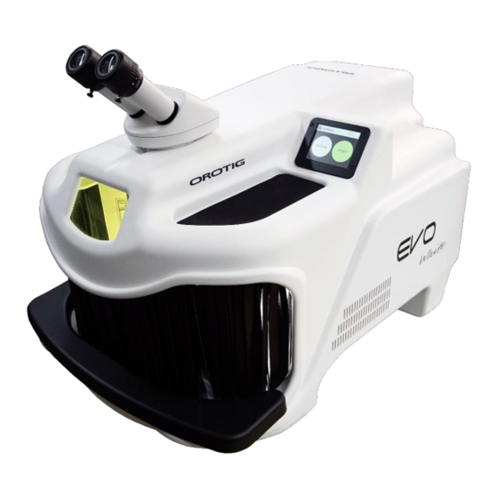
LASER welder
Operator Manual
This equipment has been designed in accordance with IEC 61010-1 and IEC 60825-1 safety regulations to prevent operator accidents
if correctly and properly used. However, no engineering design can make this equipment safe if it is not used and maintained with
due care and according to standards. This manual must be carefully and thoroughly read before performing any operation. Failure
to follow the instructions and safety regulations can cause damage to the operator and to the equipment.
MAN00077-02-EN
Advertisement
Table of Contents

Related Manuals for OROTIG EVO White


Summary of Contents for OROTIG EVO White
- Page 1 LASER welder Operator Manual This equipment has been designed in accordance with IEC 61010-1 and IEC 60825-1 safety regulations to prevent operator accidents if correctly and properly used. However, no engineering design can make this equipment safe if it is not used and maintained with due care and according to standards.
-
Page 2: Table Of Contents
Contents General information ...................................... 4 Identification .........................................................4 Safety information ......................................5 General safety rules ......................................................5 Protections..........................................................7 Interlock contact......................................................7 Leather barri e r......................................................7 Resonator shutter ......................................................7 Infra-red microscope filter..................................................8 Welding chamber infra-red filter ..............................................8 Emergency button.....................................................8 Enabling key/PIN......................................................8 Hazardous areas and residual risks .................................................8 General rul e s.........................................................8 Before all use of the equipment................................................8 Transportation precautions..................................................8... - Page 3 Operator Manual Saving the Welding Parameters................................................20 Saving the parameters..................................................20 Operation of the accessories ...................................................22 Using the protection air/gas supplier............................................22 Maintenance ......................................22 Periodic inspections.......................................................22 Checking the coolant....................................................22 Checking the filters ......................................................23 Replacing the air filter ....................................................23 Replacing the mirror protection glass slide .............................................24 Align the crosshair......................................................24 Checking alignment....................................................24 Correcting alignment....................................................24...
-
Page 4: General Information
N ote indicates that the text provides additional information, explanations or helpful tips. Identification Manufacturer: OROTIG S.p.A. Via XXV Aprile 47 37014 – Cavalcaselle di Castelnuovo del Garda Tel: +39 045 6400865, FAX +39 045 6401104 Email: info@orotig.com – web: www.orotig.com Equipment: BE0125EL BE0125EV BE0160EL BE0160EV... -
Page 5: Safety Information
Immediately stop operations in the event of an unexpected event. Stop the device immediately if a problem occurs or a burning smell is perceived, an abnormal noise is heard, abnormally hot parts are present or smoke is seen, etc. Electric shock or fire hazard. Contact OROTIG S.p.A. immediately. - Page 6 Operator Manual The welding processes produce fumes and gases. Inhaling them can be hazardous to health. Keep the head away from the fumes. Do not inhale the fumes. Do not cover the vents on the equipment. Carefully read the instructions supplied concerning the various types of metals, detergents and protection gases. The equipment should ideally be installed in a large, specially dedicated room.
-
Page 7: Protections
Operator Manual Protections All the safety measures that consist in the use of specific technical means (guards, safety devices) to protect persons from hazards that cannot be reasonably limited through design are considered as protections. Tampering with protections or any modification of the equipment can cause risks for the users and for other exposed persons. Interlock contact Description The interlock is a switch with normally closed contact, which must be positioned on the access door/s to the... -
Page 8: Infra-Red Microscope Filter
Operator Manual Infra-red microscope filter Description This filter is a 1.064 nm optical glass that is opaque to LASER radiation. It appears light grey and transparent to our eyes. It is inside the microscope. Purpose This filter protects the operator's eyes from leaks of LASER radiation along the optical path of the microscope. Operation Since it is opaque at the wavelength of 1.064 nm, it prevents the passage of LASER radiation. -
Page 9: Packaging Precautions
Operator Manual • Risk or danger Foreseen PPE Hand or limb crushing Reinforced gloves, protective overalls Abrasion, cut Reinforced gloves Vision damage due to projection of material Protective goggles and overalls Packaging precautions Keep the original packaging for future use. Always package the equipment for transport and/or handling. - Page 10 Operator Manual • Package contents The following items are found in the package: Stainless steel plate 40x30, thickness 1.5 mm SLXA1001 4 PCS Protective glass slide BK7 AR @ 1064 nm D.40 2 mm Laser ATE00043 1 PCS protection LTS 2.5 and 3.0 hex wrenches GAL01000 and GAL01001 2 PCS Microscope eye pieces...
-
Page 11: Installation
Operator Manual Installation Transport The indications contained in this paragraph must be observed when transporting the Laser Welder for: Storage • First installation • Relocation • The machine is normally supplied complete with special packaging that allows for easy transport and handling. Crates should be handled with lifting vehicles with due care and strictly respecting the direction indicated on the packaging. -
Page 12: Electric Connection
Operator Manual Electric connection Before connecting the power cable, be sure to have a proper power outlet. Make sure that the electrical outlet of the mains supply is the Schuko type; and is dimensioned on the basis of the characteristics of the equipment. -
Page 13: Equipment Specifications
"Non-declared uses”. The protection gas recommended for the welding procedures Argon. Only use original Orotig S.p.A. parts and consumables. For technical assistance, contact Orotig S.p.A. Once the consumables have worn out, they must be replaced. Follow all of the prescriptions and the safety standards indicated in this manual. -
Page 14: Non-Declared Uses
Operator Manual Non-declared uses Do not modify the equipment. Do not weld metals or alloys that include one of the following materials: Beryllium, Uranium, Plutonium, Cadmium, Magnesium, Sodium, Mercury, Potassium, Lead, Arsenic. Do not use toxic or inflammable gases such Hydrogen, Oxygen, Fluorine, Chlorine, every type of hydrocarbon gas, any mixture of Hydrogen Nitrogen. - Page 15 Operator Manual High voltage warning label ETI00130 The following devices are used on the equipment: KG3 LASER radiation protection glass, under the microscope • Leather curtains for access to the welding chamber. • • LASER radiation protective glass on inspection window •...
-
Page 16: Operator Interface
Operator Manual Operator interface Controls and signals Stereo microscope. Liquid cooling system; do not cover the vent, leave at least Inspection window with filter for LASER beams at 1064 nm. 5 cm between the vent and the wall. Hands entrance. Coolant level, for correct efficiency of the equipment: the Touch-screen display for setting welding parameters. -
Page 17: Use
Operator Manual See the Safety Information chapter before using the equipment. Recommendations Before proceeding with the normal equipment use, we recommend you check that it was correctly installed and in good working conditions. Check that its parts are not defective, damaged or worn; if necessary carry out all the necessary routine and extraordinary maintenance operations. Positioning and ergonomics Microscope eye pieces Remove the caps that protect the stereo microscope, insert the eyepieces and, once positioned in their seat, tighten the fixing screw. -
Page 18: Display
Operator Manual Display Stand-by Menu After the initial screen, the LASER is in Stand-by and the following screen appears. The device status bar informs the user of the device status (Stand-by, Ready, etc.), the current date and time, the temperature of the cooling liquid etc. -
Page 19: Sanitisation
Operator Manual Pr e-gas: In the menu in question, it is possible to set the operating mode of the solenoid valve that checks the protection GAS supply. If OFF is selected, the solenoid valve activates simultaneously with the LASER shot when the pedal is pressed. If ON is selected, pressing the pedal activates the solenoid valve. -
Page 20: Work Session
Operator Manual Work session Press the START key on the initial menu (STAND-BY) to begin the work session. An hourglass indicates to wait because verifications and preparation for the start of the session are in progress. Once this phase has been completed, the welder is ready and the following screen appears: The Power, Time, Freq, Spot, Wave form, Post-Gas, + and - keys can be selected from the Touch-screen and the Joy-stick, which is found inside the welding chamber. - Page 21 Operator Manual To recover the Silver parameters and take them into the Work session, press the key.
-
Page 22: Operation Of The Accessories
Operator Manual Operation of the accessories Using the protection air/gas supplier All of the Laser Welders are supplied with: A flexible pipe to direct the protection air or gas (1). • A glass slide-holder without dispenser (2). • It is possible to use one system or the other for the supply of the protection gas or cooling air. The outlet of the gas/air is controlled by a solenoid valve, which is activated by pressing the pedal if the "GAS"... -
Page 23: Checking The Filters
Operator Manual Removing the liquid Slide the small pipe, present on the bottom of the machine, out. Remove the cap (see photo); position the recipient under the manifold and wait for the tank to empty completely. The circuit contains approx. 2 litres of liquid. Topping-up the liquid Re-position the previously-removed cap on the bottom of the manifold, using the wrench supplied. -
Page 24: Replacing The Mirror Protection Glass Slide
Operator Manual Do not cover the vents with cloths or other materials. Leave a space of at least 10 cm between the vents and the walls. The efficiency of the Laser Welder could be compromised. Replacing the mirror protection glass slide Check the status of the glass slide inside the welding chamber at least once a month. -
Page 25: Extraordinary Maintenance
Extraordinary maintenance Extraordinary maintenance is envisioned only following an anomaly. Consult the Diagnostics chapter for additional information Extraordinary maintenance may only be carried out by OROTIG S.p.A. personnel or authorised by the same. Recommendations For a good Laser Welder efficiency, we recommend: Installation in an environment not too hot and away from heat sources;... -
Page 26: Diagnostics
Operator Manual Diagnostics Errors and warnings If one of the following messages appears on the display, operate as described in the "Solution" section of the message. E rror 1: H2O flux failure Pr oblem: The flow sensor does not detect any liquid in the cooling circuit S olution: Check the correct level of the liquid Check the water filter is not clogged... - Page 27 Operator Manual W arning 4: USB Pendrive not found S ymptom: The pendrive has not been detected in the relevant housing. S olution: Check the correct insertion of the pendrive in the housing. If it is not detected or the Pendrive is not inserted, the data of the current work session cannot be saved.
-
Page 28: Note
Operator Manual Note: © 2021 Orotig S.p.A. All rights reserved Revision: Issue date 12/02/2020 S.P. 18/09/2020 S.P. 01/04/2021 S:P.
Need help?
Do you have a question about the EVO White and is the answer not in the manual?
Questions and answers
Good day! We have an Evo White installation and the error 01 popped up the water level is normal, we have completely changed the water, the instructions say to check the water filter, but it is not clear how to do this. please help me figure out what is the cause of the error. I have attached the video Thank you
Error 01 on the OROTIG Evo White installation is caused by a problem in the cooling circuit.
To check the water filter:
- Ensure the liquid level is correct.
- Inspect the water filter to confirm it is not clogged.
If the issue persists, contact technical after-sales assistance.
This answer is automatically generated