
Related Manuals for QSC Q-SYS NL-SB42


Summary of Contents for QSC Q-SYS NL-SB42
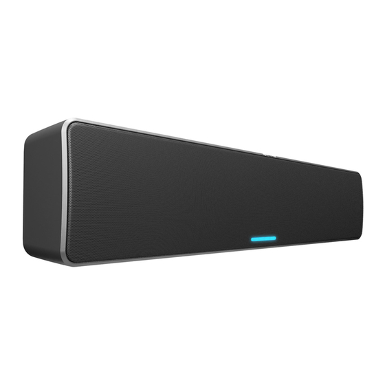
- Page 1 ® ™ Hardware User Manual NL-SB42 4” Two-way Network Soundbar TD-001638-01-A *TD-001638-01*...
-
Page 2: Important Safety Instructions
QSC authorized service station or an authorized QSC international distributor. QSC is not responsible for any injury, harm or related damages arising from any failure of the customer, owner or user of the apparatus to facilitate those repairs. -
Page 3: Specifications And Dimensions
The QSC Q-SYS NL-SB42 is in compliance with European Directive 201 1/65/EU – Restriction of Hazardous Substances (RoHS2). The QSC Q-SYS NL-SB42 is in compliance with “China RoHS” directives per GB/T 26572. The following chart is provided for product use... -
Page 4: What's In The Box
What’s in the Box (1x) (1x) (2x) NL-SB42 Wall mount bracket Rubber feet and screws (4x) (1x) (1x) Wall isolation washers Warranty statement Safety information Connections and Controls Front LED Light Bar: Indicates the status of the NL-SB42. — Figure 1 — Rear Q-LAN/PoE Port: For Q-LAN connection. -
Page 5: Freestanding Installation
IMPORTANT! Mount to a surface capable of supporting the weight of the soundbar. WARNING: Install the system in accordance with local building codes and regulations. Use a licensed contractor or professional engineer. QSC, LLC is not responsible for damages resulting from the negligent installation of any bracket or loudspeaker. Soundbar Mounting Features Refer to Figure 5. -
Page 6: Mount The Bracket
Mounting and Cabling Options You can mount the soundbar horizontally or vertically, with the Ethernet cable routed through the wall (directly behind the bracket) or through the bracket’s Cable Pass Notch. For ease of access when releasing the speaker from the bracket in the horizontal position, it is recommended to position the bracket with the Release Latches (Figure 6) on the bottom. - Page 7 Connect the Cable Attach the Soundbar Before mounting the speakerbar, plug the Ethernet cable’s RJ45 Push the soundbar onto the wall bracket. The Wall Bracket Bars on connector securely into the jack on the back of the enclosure (Figure the soundar will snap and lock onto the wall bracket (Figure 12). 1 1).
-
Page 8: Confirm Connections
Tighten the Safety Lock Screws For safety and security, tighten the Safety Locking Screws on both sides of the wall bracket (Figure 16). — Figure 16 — Release the Soundbar To remove the soundbar from the wall bracket, press the Release Latches located on the top or bottom of the bracket, depending on the orientation (Figure 17). -
Page 9: Customer Support
For a copy of the QSC Limited Warranty, visit the QSC, LLC., website at www.qsc.com. © 2022 QSC, LLC. All rights reserved. QSC and the QSC logo, Q-SYS, and the Q-SYS logo are registered trademarks of QSC, LLC in the U.S. Patent and Trademark Office and other countries.
Need help?
Do you have a question about the Q-SYS NL-SB42 and is the answer not in the manual?
Questions and answers