QSC KLA12 User Manual
Qsc kla series active line array loudspeaker
Hide thumbs
Also See for KLA12:
- User manual (26 pages) ,
- Quick start manual (6 pages) ,
- Quick start manual (4 pages)

Related Manuals for QSC KLA12


Summary of Contents for QSC KLA12
-
Page 1: User Manual
KLA Series User Manual KLA12 – 12" 2-way Loudspeaker KLA181 – 18" Subwoofer KLA AF12 – Array Frame TD-000319-00-A *TD-000319-00*... -
Page 2: Explanation Of Symbols
WARNING!: TO PREVENT FIRE OR ELECTRIC SHOCK, DO NOT EXPOSE THIS EQUIPMENT TO RAIN OR MOISTURE. WARNING!: While it is possible for one person to lift a KLA12 loudspeaker, it is important to use proper lifting techniques. Suggested reading: OSHA Technical Manual on Back Disorders and Injuries (http://www.osha.gov/dts/osta/otm/otm_vii/otm_vii_1.html#app_vii:1_2). -
Page 3: Fcc Statement
Damage to, or loss of any software or data residing on the product is not covered. When providing repair or replacement service, QSC will use reasonable efforts to reinstall the product’s original software configuration and subsequent update releases, but will not provide any recovery or... - Page 4 Use the KLA AF12 Array Frame or the M10 Integrated Suspension points to suspend one KLA Array consisting of one of the following three array configuration options. The maximum number of KLA12 Loudspeakers in any array, with or without KLA181 Loudspeakers, is five.
- Page 5 The KLA Series is comprised of two models: the KLA12 12-inch, 2-way loudspeaker and the KLA181 18-inch subwoofer. The KLA12 features a highly efficient 500 W x 500 W power-amp module in a rugged, lightweight ABS enclosure that can be used in multiple configurations using QSC's unique SOLO™...
- Page 6 Features KLA12 — Figure 1 — 1. ABS enclosure 6. M10 installation points (3) 2. Steel grille 7. Tilt-Direct™ dual angle (0° or -9°) pole socket 3. Front power LED 8. Slip-resistant feet 4. Handles 9. Side Rigging Plates 5. Power module...
- Page 7 KLA181 0˚ -9˚ — Figure 2 — — Figure 3 — — Figure 4 — 0˚ — Figure 5 — 1. Baltic Birch enclosure 6. M10 installation points (4) 2. Steel grille 7. Slip-resistant feet 3. Front power LED 8. M20 threaded, 35 mm pole mount 4.
- Page 8 KLA AF12 (Shown as shipped) 1. Rigging pins and lanyard (2) 2. Array extension beam 3. Array frame 4. Feet for KLA181 application 5. Feet for KLA12 application — Figure 6 —...
- Page 9 KLA12 ensures a 0° angle making it ideal for front fill, or stage lip deployment (Figure Preparing the KLA for Suspension WARNING!: The KLA181 weighs 104 lbs. (47.2 kg) and the KLA12 weighs 55 lbs. (25 kg) Use proper lifting techniques to complete this procedure. Refer to "KLA Maximum Suspended Load" on page WARNING!: Make sure that the loudspeakers are properly aligned;...
- Page 10 Locked Position. If not properly latched, the loudspeakers could separate and cause physical damage to the loudspeakers, and/or personal injury. 8. Repeat the procedure for the other side of the loudspeaker, and for all KLA12 loudspeakers in the array. The loudspeakers are ready to suspend.
- Page 11 The KLA12 cannot be attached to the top of a KLA181. There are various ways to facilitate attaching a KLA12 to a KLA181, and they vary depending on the specific circumstances. Be sure to use proper rigging techniques, and/or employ a professional engineer. Following is one example.
- Page 12 Separating a KLA12 from a KLA AF12 Array Frame, KLA12, or KLA181 Refer to Figure 1. Safely support the bottom KLA12 in the array. You must support both sides of the loudspeaker, and relieve the weight of the loudspeaker from its latching mechanism in order to separate one loudspeaker from another.
- Page 13 Attaching a KLA181 to a KLA AF12 Array Frame Refer to Figure 18 NOTE: The KLA AF12 Array Frame must be oriented with the KLA181 feet pointing down as shown in Figure 18. For more detail, refer to Figure 3 on page 8. 1.
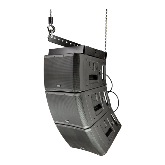
- Page 14 You can suspend a KLA Array in one of two ways: using the KLA AF12 Array Frame, or using Integrated Suspension points and eyebolts. Using the KLA AF12 Array Frame You can attach the KLA AF12 Array Frame to the KLA12 or the KLA181 for suspension. Extended Portion...
- Page 15 Refer to Figure 25 You can mount up to two KLA12 loudspeakers on a loudspeaker pole over the KLA181 or KW181 subwoofer, or on a loudspeaker tripod. To mount over a KLA181 or KW181 subwoofer: 1. Thread the loudspeaker pole into the M20 threaded, 35 mm pole mount on the top of the KLA181 subwoofer. Hand tighten.
-
Page 16: Audio Connections
2. Carefully place one KLA12 on the loudspeaker pole by inserting the pole completely into the QSC Tilt-Direct™ pole socket. Use proper lifting techniques. 3. If you want to mount two KLA12 loudspeakers on the pole, after you place the first loudspeaker on the pole, attach the top one using the procedure "Attaching a KLA12 to a KLA12 or KLA AF12 Array Frame"... -
Page 17: Making Audio Connections
Always follow the rule that loudspeakers are “last on, first off”. NOTE: The KLA12 employs a universal power supply, capable of operating the system with input AC power voltages ranging from 100 –... -
Page 18: Power-On Sequence
WARNING!: Do not connect more than five KLA Series loudspeakers together using the loop-thru power cables (four loop- thru cables, one AC power cord). If you are using loop-thru power cables, make all loop-thru connections prior to connecting to the AC mains. 3. -
Page 19: Rear Led Indicators
These functions include crossovers, time alignment, limiting and protection, thermal management some of which are implemented using a number of proprietary features. QSC has designed exclusive DSP functions that greatly enhance the capabilities and... -
Page 20: Subwoofer Polarity
Polarity can be altered by incorrect wiring or mixer control settings. When using the KLA181 with KLA12 full range loudspeakers, NORMAL polarity will result in the best bass response IF the full range loudspeakers are very close to the subwoofers, for example, stacked on top of, in the same vertical array, etc. If the subwoofers are some distance away from the full range loudspeakers, polarity change may be of benefit. -
Page 21: Additional Features
Additional Features Front LED Switch The blue power LED, on the front of the loudspeakers, may be set to any of three modes by the FRONT LED switch (Figure 33) located on the amplifier panel. PWR – This is the factory setting which means the LED illuminates when the POWER switch is in the ON position and the unit is not in STANDBY. - Page 22 Wiring the Remote Attenuator Single Loudspeaker Multiple Loudspeakers Proper Wiring 1 = +5V 1 2 3 — Figure 38 — Wire the Remote Gain Attenuator as shown in Figure 35. When using a single potentiometer for a Single Loudspeaker (A). When using a single potentiometer for Multiple Loudspeakers (B).
- Page 23 Dimensions KLA12 Side Front 16.6 in (422 mm) 23.4 in (594 mm) — Figure 39 — KLA181 Side Front 25.7 in (653 mm) 23.4 in (594 mm) Side with Optional Casters 30.0 in (762 mm) — Figure 40 —...
-
Page 24: Specifications
Specifications KLA12 KLA181 Configuration 2-way line array element 18" ported subwoofer Transducers Low-frequency 12" cone transducer 18" cone transducer High-frequency 1.75" diaphragm compression driver — Frequency Response (-6 dB) 49 Hz – 18 kHz 38 Hz Frequency Range (-10 dB) 44 Hz –... - Page 25 © 2011 QSC Audio Products, LLC. All rights reserved. QSC™ and the QSC logo are registered trademarks of QSC Audio Products, LLC in the U.S. Patent and Trademark office and other countries. Tilt-Direct, Intrinsic Correction, DEEP and GuardRail are all trademarks of QSC Audio Products, LLC. powerCON is a registered trademark of Neutrik.
Need help?
Do you have a question about the KLA12 and is the answer not in the manual?
Questions and answers