Advertisement
Quick Links
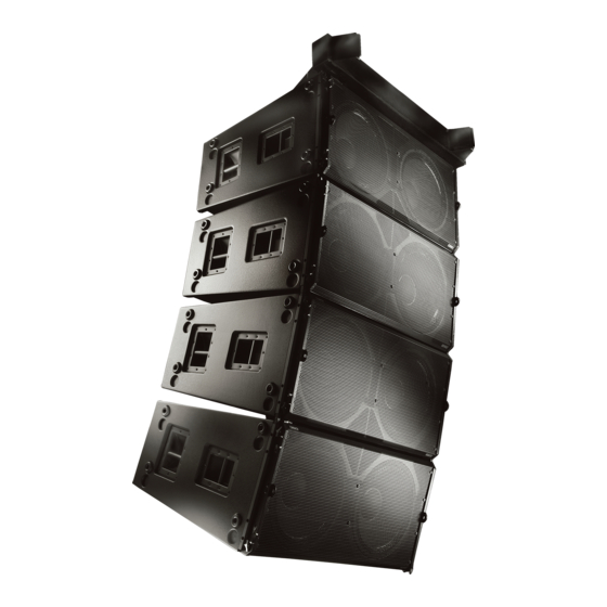
WideLine Series Loudspeaker System User Manual
WL218-sw
subwoofer line array loudspeaker
DB218-sw
dolly board
AF218-sw
subwoofer array frame
*TD-000232-00*
TD-000232-00 revB
1675 MacArthur Blvd., Costa Mesa, CA, 92626 USA
Main Number (714) 754-6175 Sales & Marketing (714) 957-7100 or toll free (USA only) (800) 854-4079
Customer Service(714) 957-7150 or toll free (USA only) (800) 772-2834
Advertisement

Subscribe to Our Youtube Channel
Summary of Contents for QSC WL218-sw
- Page 1 Main Number (714) 754-6175 Sales & Marketing (714) 957-7100 or toll free (USA only) (800) 854-4079 Customer Service(714) 957-7150 or toll free (USA only) (800) 772-2834 WideLine Series Loudspeaker System User Manual WL218-sw subwoofer line array loudspeaker DB218-sw dolly board...
-
Page 2: Important Safety Precautions
QSC Audio Products 3 Year Limited Warranty QSC Audio Products, LLC (“QSC”) guarantees its products to be free from defective material and / or workmanship for a period of three (3) years from date of sale, and will replace defective parts and repair malfunctioning products under this warranty when the defect occurs under normal installation and use - provided the unit is returned to our factory or one of our authorized service stations via prepaid trans- portation with a copy of proof of purchase (i.e., sales receipt). - Page 3 Transport and handling features are also provided in the WL218-sw's design. No matter how the box is deployed, one of the dozen han- dles will be where it needs to be. The included dolly has rugged, 3.5-inch ball bearing casters and an easy-to-use, snap-on mechanism for attachment to the enclosure.
- Page 4 Introduction (continued) DB115-sw Dolly Board 1- Pads 2- Casters 3- Stacking Recesses 4- Latches 5- Handling Cut-outs 6- Handles AF218-sw Array Frame 1- Ground stacking bumpers 2- Center support bar 3- Shackle holes (accept 3/4” (20 mm) screw pin anchor shackle) Use only shackle holes for suspension of array! 4- Rigging plate, retaining bolts, and link assembly with ball lock pin 5- Receiver blocks...
-
Page 5: Shock Loading
Dynamic conditions are determined by unknown, installation-specific factors and should be referred to a Licensed Struc- tural Engineer for clarification before proceeding with any suspension of the equipment. The data presented is based upon the listed component weights: Table 1: WideLine WL218-sw System Working Load Limits Component WL218-sw Loudspeaker 206 lb (93.4 kg) - Page 6 NOTE: All hardware/components must be rated for the expected loads as determined by the Professional Engi- neer responsible for suspension. Attaching WL218-sw Loudspeaker to WL218-sw Loud- speaker 1- With the enclosures on dolly boards and facing downward, posi- tion two enclosures adjacent one another such that the front receiver tubes are aligned.
- Page 7 Rigging (continued) Adjusting the Angle Between Enclosures (Splay) The illustration below shows the rear receiver block of two enclosures joined by the upper enclosure’s rear link (enclosures and ball lock pin lanyards omitted for clarity). Note the link is marked in two locations when extended. The unlabelled white line nearest the end of the link is the normalized (or 0°) hole position marker.
- Page 8 Array Frame Ground Stacking with the AF218-sw The AF218-sw array frame can be used for ground stacking up to four WL218-sw enclosures. There is no recommended proce- dure other then the requirement that all articulated joints, links, and ball lock pins be in their normal position (as if sus- pended) and be fully inserted and locked into position.
-
Page 9: Input Connections
WL218-sw Controls and Connections Input Connections The WL218-sw input connectors are a pair of Neutrik NL4's wired in parallel. See Table 2 or the WL218-sw Input Plate for connector pinout. Note pin numbers 2+ and 2- are wired straight through from one connector to the other. - Page 10 WL218-sw Specifications Configuration: Transducers: Frequency Response Frequency Range Impedance: Continuous Power Capacity Sensitivity (1W at 1m) Maximum SPL (continuous/peak) Enclosure Type: Enclosure Material: Finish: Grille: Connectors: Factory wiring: Attachment Points: Weight: Working Load Limit Information: Component WL218-sw Loudspeaker Notes: ±3dB relative to sensitivity, based upon half-space conditions, without external processing...
- Page 11 DB218-sw Specifications Material: Finish: Weight: AF218-sw Specifications Material: Finish: Working Load Limit Information: Component AF218-sw Array Frame Dimensions- WL218-sw 35.740” (907.8mm) 34.750” (882.65mm) (1166.37mm) Baltic birch plywood. 0.75-inch (18mm) Polymer paint, water based Net: 30 lb (13.6 kg) Aluminum 6061-T6...
- Page 12 Dimensions- DB218-sw Dimensions- AF218-sw...
-
Page 14: How To Contact Qsc Audio Products
(714) 754-6174 Customer Service FAX (714) 754-6173 World Wide Web: www.qscaudio.com E-mail: info@qscaudio.com service@qscaudio.com QSC Audio Products, LLC 1675 MacArthur Boulevard Costa Mesa, California 92626 USA ©2006 “QSC” and the QSC logo are registered with the U.S. Patent and Trademark Office.


Need help?
Do you have a question about the WL218-sw and is the answer not in the manual?
Questions and answers