Advertisement
Quick Links
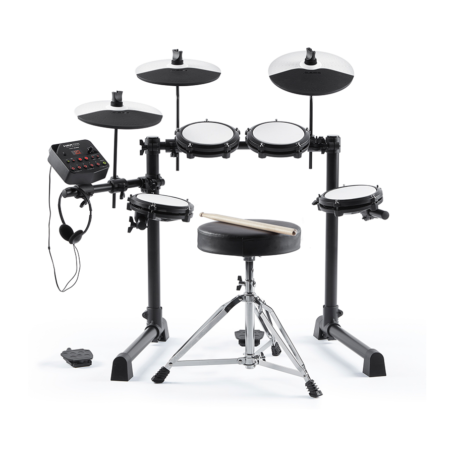
E-Drum Total
This document contains sensitive proprietary information.
All recipients must have a current non-disclosure agreement
on file with Alesis.
Do not make illegal copies of this document.
The information in this document contains privileged and confidential information. It is intended
only for the use of those authorized by Alesis. If you are not the authorized, intended recipient,
you are hereby notified that any review, dissemination, distribution or duplication of this
document is strictly prohibited. If you are not authorized, please contact Alesis and destroy all
copies of this document. You may contact Alesis at support@alesis.com.
© Copyright Alesis
Confidential
Alesis
[LDLY]
Service Manual
v1.0
2020-09-23
ATTENTION!
Alesis Service Manual
Advertisement

Related Manuals for Alesis E-Drum Total


Summary of Contents for Alesis E-Drum Total
- Page 1 The information in this document contains privileged and confidential information. It is intended only for the use of those authorized by Alesis. If you are not the authorized, intended recipient, you are hereby notified that any review, dissemination, distribution or duplication of this document is strictly prohibited.
- Page 2 Your purchase of the Manual shall be for your own ultimate use and shall not be for purposes of resale or other transfer. As the owner of the copyright to the Manual, Alesis does not give you the right to copy the Manual, and you agree not to copy the Manual without the written authorization of Alesis. Alesis has no obligation to provide to you any correction of, or supplement to, the Manual, or any new or superseding version thereof.
- Page 3 ALL REPAIRS DONE BY ANY ENTITY OTHER THAN AN AUTHORIZED ALESIS SERVICE CENTER SHALL BE SOLELY THE RESPONSIBILITY OF THAT ENTITY, AND ALESIS SHALL HAVE NO LIABILITY TO THAT ENTITY OR TO ANY OTHER PARTY FOR ANY REPAIRS BY THAT ENTITY.
- Page 4 The product is exposed to water or excessive moisture, c. The AC power supply plug or cord is damaged, d. The product shows an inappropriate change in performance or does not operate normally, or e. The enclosure of the product has been damaged. Confidential Alesis Service Manual...
- Page 5 DIGITAL DRUM LDLY crash ride hi-hat tom 3 snare hi-hat kick control control SERVICE MANUAL...
-
Page 6: Table Of Contents
Contents Panel & Display descriptions......................3 General Exploded Drawing and List....................5 Assembly Exploded Drawing and List...................6 Circuit Boards..........................1 0 Parts List............................1 4 PCB Boards..........................20 Diagnosis............................22 Frequently Asked Questions.......................28... -
Page 7: Panel & Display Descriptions
Panel Description Top Panel Power Button: Press this button to turn the drum module on. Press and hold it for 2 seconds to turn the drum module off. Display: This screen shows information relevant to the drum module's current function and operation. - Page 8 Panel Description Rear Panel Power Jack: Use the included power adapter (9 V, 500 mA, center pin-positive) to connect this jack to your power outlet. Cable Snake Input: Connect the head of the included cable snake here. Connect the cables at the tail end of the cable snake to your kit's triggers (drum pads, cymbal pads, and pedals).
-
Page 9: General Exploded Drawing And List
General Exploded Drawing and List... -
Page 10: Assembly Exploded Drawing And List
Assembly Exploded Drawing and List... - Page 11 Assembly Exploded Drawing and List...
- Page 12 Assembly Exploded Drawing and List spec. Description. QTY.
- Page 13 Assembly Exploded Drawing and List...
-
Page 14: Circuit Boards
Circuit Boards Main Board Schematic-01... - Page 15 Circuit Boards Main Board Schematic-02...
- Page 16 Circuit Boards Board Schematic...
- Page 17 Circuit Boards Function Board Schematic-1 Function Board Schematic...
- Page 18 BB 2.6*8BB black “+” PWB no harden 14.00000 PCS T=0.8MM PC 59.7*139.4mm Black background 642010689 Lens silkscreen white Windows transparent gray 1.00000 PCS ALESIS 10103036502 Function board ASSY DD401L 1.00000 SET ++++ 619030012 3bit digital LED red WEJE30561-I00W-1 anode 1.00000 PCS DIG701...
-
Page 19: Parts List
Parts List 10uf/50V +20% -20% BIPOLAR PIN length ++++ 60308001001 CAP ELECT DIP 1.00000 PCS C114 3.5+/-0.3MM 47uf/25V +20% -20% 5*11mm PIN length 3.5+/- ++++ 60308005801 CAP ELECT DIP 1.00000 PCS C101 0.3MM 100uf/16V +20% -20% 5*11mm PIN length ++++ 60308001101 CAP ELECT DIP 1.00000 PCS C108 3.5+/-0.3MM... - Page 20 Parts List +++++ 603010166 CAP CERAMIC SMD 200pf/50V +10%-10% 0603 2.02000 PCS C308-309 +++++ 603010121 CAP CERAMIC SMD 1200pf/50V +10%-10% 0603 2.02000 PCS C305-306 C332-333 C336-337 C404 C407 C409 C411 C414 C417 +++++ 603010009 CAP CERAMIC SMD 0.001uf(1000pf)50V +10% -10% 0603 SMD 20.20000 PCS C420 C423 C425 C427 C601-606...
- Page 21 Location slot after changed 1.00000 PCS 1616 RD090270 outsize:138*59*24.5mm Black fan 40 ° silicone surface texture with 629990483 10”silica gel ALESIS LOGO for the bright surface 1.00000 PCS 252.4*135*20mm 629990368 Cymbal location Black silica gel 65°N/A out size:φ59*19.5mm 1.00000 PCS 254*136.2mm sector middle with hole Crown...
- Page 22 Parts List Cymbals I/O Board ASSY(SMT 10110068901 DD512 with SMK Audio Jack without choke 1.00000 PCS Part) DD512 Cymbal I/O board V04 white silkscreen ++++ 506040638 PCB Dual layer FR4 1.6mm green oil Lead-free tin spray FR4 196*98*1.6mm 1.00000 PCS 14 boards/panel ++++ 602010150...
- Page 23 5X5 inch 400g of copper plate brightness to half 1.00000 PCS 300g pink gray K3A3 647000894 Giftbox 1.00000 PCS dieline:730*690*220mm(LWH) ALESIS UV Five language 5.5*8.5 inch 80g ALESIS 7-51- 640000497 Safety and warranty manual 1.00000 PCS 1308-H Without FCC 643010179 Bone closure Polybag PE 230*340*0.03mm printing warning...
-
Page 24: Pcb Boards
PCB Boards Main Board-1 Main Board-2... - Page 25 PCB Boards Function Board Schematic...
-
Page 26: Diagnosis
Diagnosis Test Conditions Power input: DC 9.0±0.5V Equipment: an oscilloscope, headphones/speakers, USB-MIDI cable, audio cable. Volume: Adjust the volume knobs to maximum. 2. Self-test Cosmetic Check 1. Check if there is scarring on the panel (including buttons, knobs and the display). 2. - Page 27 Diagnosis Press [+] button, the display will show the PCBA version. To go back to the software version, press the [-] button. Press the [START/STOP] button to enter the main test menu. The display will show the first test item. ...
- Page 28 Diagnosis This image indicates the L and R channels are muted. FUNCKEY Press the [+]/[-] buttons to select “C02”, then press [ ] to start this test. Press [+] and [-] at START/STOP the same time to exit.
- Page 29 Diagnosis This chart shows the button names and the corresponding button values. Button name Value Button name Value CLICK 1 START/STOP 2 ‐ 3 + 4 PATTERN 5 TEMPO 6 SLOW 1 7 SLOW 2 8 GOOD 3 9 GOOD 4 10 FAST 5 11 VARIATION 12 LED Press the [+]/[-] buttons to select “C03”, then press [START/STOP] to start the test. The panel LEDs will turn one by one, then finally all LEDs turn on.
- Page 30 Diagnosis Before starting this test, make sure the SN and date are already burned to the instrument. In this test, the LED display will show the SN in three pages: Sn/x.xx/xx.x; and show the date in another three pages: year (.xx), month (x.x), date (xx.). Use the [+]/[-] buttons to flip the pages.
- Page 31 Diagnosis This image indicates there is an error (only two of the dots light up). This image shows the error details. This error number corresponds to the USB-MIDI jack. Detailed errors and error numbers: Error ...
-
Page 32: Frequently Asked Questions
1. Can’t boot 1. Check the voltage of PIN 1 of IC101(7805),the voltage should be equal to 9V +/- 15% and the voltage of PIN 3 should be equal to 5V +/-10% ,if not, check the relevant circuit elements. 2. Check the IC102 (LM1117) in the main board, the pin 2 should be equal to 3.3V+/-10%. If not, check the relevant circuit elements or replace the IC102 3. - Page 33 If there is no sound in any case, the error may be in the main chip or the line of AMP. Only strike the drum Check the signal of pin 75/76/78 in the IC201. Strike the drum; Check the signal of pin 75/76/78 in the U10 .If the signal is normal, check the relevant circuit elements of drum.
- Page 34 If above is ok,check in accordance with 2.1. 4. Function keys error Check the connections of keys, and check the welding of AR217 ~ A220. Check the signals of PIN 1~5 in CON701, the output is pulse. If no keys be pressed, the signal of PIN 6/7/8 in CON701 is low. If un-normal, check whether short cut or open circuit between resisters and capacitors.
- Page 35 6. Data Memory error Check the power and grand in IC203. Check the signals: IC203.1, IC203.2, IC203.3, IC203.7, the output should be low, the output of IC203.5 and IC203.6 are high. If above is ok, replace the IC203. 7. USB Jack error 1.
Need help?
Do you have a question about the E-Drum Total and is the answer not in the manual?
Questions and answers