Table of Contents
Advertisement
Quick Links
Advertisement
Table of Contents

Related Manuals for Rehabed TAURUS 2


Summary of Contents for Rehabed TAURUS 2
-
Page 3: Table Of Contents
8.5. E ......34 Table of contents LECTRICAL CONTROL 8.5.1. L ..36 OCATION OF THE HANDSET 8.5.2. O 1. INTRODUCTION........4 PERATION OF BUTTON AND ......... 36 1.1. C .......... 4 BUTTON HANDSETS ONTACT 8.5.3. L 1.2. W OCK FUNCTION OF THE HANDSET HAT THE INSTRUCTION MANUAL IS .............. -
Page 4: Introduction
In order to receive support outside of Poland, please contact the importer or the local distribution company, which sold you the device. 1.2. W HAT THE INSTRUCTION MANUAL IS ABOUT This instruction manual applies to Taurus 2 beds with the possibility of electric control of the back and leg sections. -
Page 5: General Information
1.4. A PPLICATION The Taurus 2 bed has been designed to provide the user with optimal independence and freedom whilst aiding the manual handling requirements of the carer. It is operated with the use of a 9- or 10-button handset. It is intended for use in the following environments: ▪... -
Page 6: Contraindications
Make sure the product is suitable for your condition or dysfunction. 1.5. C ONTRAINDICATIONS The contraindications for using the Taurus 2 bed include: ▪ Cervical or skeletal traction, ▪ Unstable fractures of the spine – if the bed’s functions remain unlocked, ▪... -
Page 7: Warnings And Cautions
2. W ARNINGS AND CAUTIONS Warnings in this instruction manual indicate potential hazards, disregard of which could lead to injury or death. Cautions in this instruction manual identify potential hazards, disregard of which could result in damage to the equipment. 2.1. - Page 8 ▪ If the product is connected to the power supply with an extension cable, never overload the product by connecting devices that exceed the maximum rating of the extension cable – risk of fire. ▪ Make sure that there are not many sockets under the frame – liquids that may seep into such a socket during normal use of the bed may pose electrical/fire hazard.
- Page 9 ▪ In the case of the event of lifting pole’s deformation, it should be immediately replaced with a new one. ▪ Pulling out the plug from the socket is allowed only when you hold the plug/adapter – do not pull the cable. ▪...
- Page 10 ▪ Due to the small space under the bed, special attention should be paid to young children, user limbs and other items around the bed that could be trapped between the bed’s components and injured or damaged. ▪ Precautions are to be taken when routing cables from external equipment around the bed to ensure that they do not become crushed, trapped or damaged - damaged cables could pose a risk of electrocution/fire.
-
Page 11: Transport And Storage
3. T RANSPORT AND STORAGE Observe the following instructions when transporting and storing the bed: ▪ Store the bed on the transport stand to save space. ▪ Always store the bed on a flat, level surface. ▪ Set the bed to the minimum height. ▪... - Page 12 ▪ In order to prevent the risk of cross contamination, when removing the bed from its place of use by the end user, make sure that all actions (connected with the bed) are carried out with the use of disposable gloves. Next to, properly dispose the glove, unless it can be verified that the bed and all accessories have been properly disinfected and cleaned.
- Page 13 ▪ Take special precautions concerning EMC. The bed should be installed and put into operation in a manner described in chapter 14. ▪ The bed with an additional source of emergency power supply is not intended to discharge batteries for a long time and it should always be connected to the power supply during normal use –...
-
Page 14: Symbols And Markings
4. S YMBOLS AND MARKINGS The following symbols are observed on the beds: Warning Warning of the potential risk Caution Warning of potential damage to the product Reference to the instruction manual - recommended Failure to comply with the recommendation may cause a risk Reference to the instruction manual - mandatory Failure to comply with the recommendation may cause a risk Maximum user weight... - Page 15 Electrical specification Including storage and use conditions Warning – removable side rail Incompatible and improperly installed side rails may pose a risk of injury or death - see the instruction manual Total product weight on the transport stand Heavy weight of the product - be careful when transporting on the transport stand and assembly Warning regarding the transport on the transport stand The risk of loss of stability/overturning of the product - be careful when transporting the...
-
Page 16: Component Parts
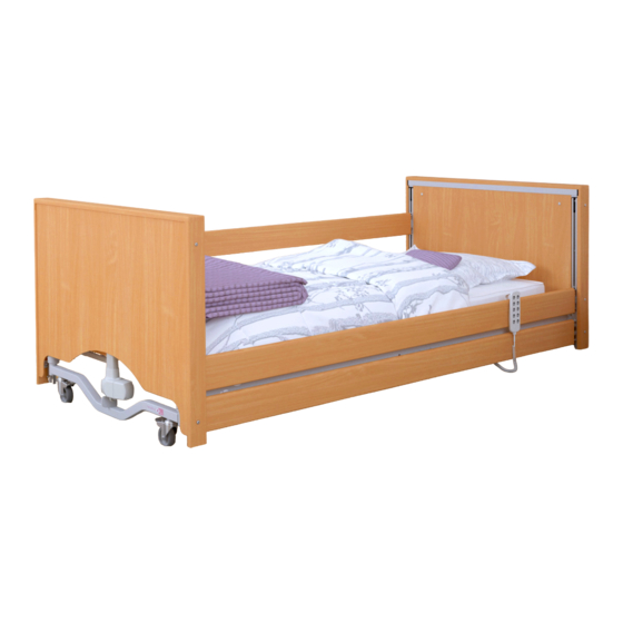
5. C OMPONENT PARTS 5.1. L IST OF COMPONENTS OF THE BED (The figure shows the Taurus2 bed with wooden side rails) 1. Bed end x2 2. Backrest section x1 3. Mattress side retainer x4 4. Leg section x1 5. Transport stand x2 6. -
Page 17: Assembly Of The Bed And Preparation For Use
6. A SSEMBLY OF THE BED AND PREPARATION FOR USE 6.1. D ISASSEMBLY FROM THE TRANSPORT STAND ▪ Make sure that you have read and fully understood the instruction manual before the assembly of the bed. ▪ Make sure that a risk assessment has been conducted in acceptance with local health and safety regulations in order to protect personnel from risks during assembly works. -
Page 18: Assembly Of The Bed
SSEMBLY OF THE BED ▪ Prior to assembling the bed the backrest actuator of the Taurus 2 must be removed and rotated 180° to change the bed from transport to in use mode. Ensure the mains cable is not in tension or... -
Page 19: Connection Of The Electrical System
The bed must never be used if the grub screws and/or clevis pins and associated ‘R’ clips are loose or missing - risk of bed collapse. Also using bed without the wooden slats installed threatens with danger of mattress collapsed. ▪... - Page 20 ▪ Once all the cables are connected they are to be secured in place by re- attaching the supplied cable cover to the control box. If removed, the battery cover is fastened into place using the supplied screw. ▪ The mains cable exiting the control unit should now be connected to the power supply plug.
- Page 21 6.3.1. C ABLE ROUTING AND ANCILLARY PRODUCT CABLE ROUTING The Taurus 2 bed is equipped with 4 holders that enable to suspend the power cable under the mattress platform. The cables are to be routed on the bed frame as shown...
-
Page 22: Assembly Of Wooden Side Rails
▪ Ensure all cables, in particular the mains cable, and ancillary cables are free from moving parts and are not under excessive tension to avoid cable damage - damaged cables can create a risk of electrocution/fire. ▪ All cables must be suspended under the mattress platform in holders designed for this purpose –... - Page 23 Top side rail block and wire assembly (for 85 mm, 95 mm Top side rail block and wire assembly (for 110,5mm and 100 mm height side rails) height side rails) ▪ Insert the top side rail block with side rail wire into one of the side rail channels until it latches in the lowest position;...
- Page 24 ▪ Slide the second (bottom) side rail over the fingers in the bottom side rail block (rounded surface facing up). Raise the side rail so it latches in the highest position at one end. Make sure that the side rail is slid enough over the fingers to prevent it from falling out.
-
Page 25: Side Rails And Mattresses
AILS AND ATTRESSES The Taurus 2 is specified with the full-length, wooden side rails; refer to sections 15.3 and 16.1 for a comprehensive list of options. When specifying a mattress and side rail combination a clinical assessment of the patient’s needs must be carried out in line with local policy. -
Page 26: Fitting Ratchet
ITTING ATCHET The Taurus 2 bed can be equipped with a ratchet to adjust the leg section angle; refer to section 16 for a comprehensive list of optional accessories. If the ratchet is supplied as an accessory with a spanner, you will also need the Allen Key provided with the bed - refer to section 5.1 for Allen key location on the bed. -
Page 27: Checking The Bed
6.6. C HECKING THE BED The bed is fully assembled now. Before it is put into use, ensure the bed has been correctly assembled by carrying out the following checks: ▪ Ensure the correct side rails are fitted to the bed. ▪... -
Page 28: Training
7. T RAINING Professional personnel should be appropriately familiarized with the functionality of the bed, its limitations and the target user group before use. The user’s ability to operate the handset in an independent manner should be determined in acceptance with the risk assessment. -
Page 29: First Use
▪ The Taurus 2 LOW bed does not meet the height range and underbed clearance requirements for the PN-EN 60601-2-52 standard. If the potential risk is implemented by the requirements of the patient of caregiver, the use of a bed with standard height should be considered. -
Page 30: General Safety
8.1. G ENERAL SAFETY ▪ Before using the bed, make sure that objects such as a bedside table or other furniture are not obstacles. ▪ Before using the bed, make sure that the user is correctly positioned. ▪ Before leaving the user without any supervision, make sure that the bed is set to the minimum height. -
Page 31: Brake System
▪ the mattress platform is placed horizontally, ▪ the handset’s functions are locked/unlocked (depending on the assessment of the patient’s condition and the environment – see section 8.5.3) ▪ the bed is placed horizontally on a flat surface so all the castors touch the ground, ▪... -
Page 32: Side Rails And Mattress
Wheels should be locked / unlocked by foot, not by hand. 8.4. S IDE RAILS AND MATTRESS Taurus 2 beds are fitted with wooden side rails along the whole length of the bed (as the standard). Characteristics of the mattresses and the side rails tested and approved by the manufacturer can be found in the section 15.3 and 16.1. -
Page 33: Height Of The Mattress
8.4.1. H EIGHT OF THE MATTRESS ▪ The standard height side rails enable to use mattress with a maximum height of 160 cm. ▪ Side rails may only be used with a mattress of the proper size and type – intended for use in electric beds. ▪... -
Page 34: Electrical Control
8.5. E LECTRICAL CONTROL The Taurus 2 bed is intended to be permanent plugged into a mains supply. A battery backup accessory is available for such times that a mains supply is not available or reliable. - Page 35 ▪ It is forbidden to use any glowing or burning objects (candles, cigarettes, etc.) in the bed’s area – the risk of damage to the electrical system leading to a fire. ▪ It is forbidden to use actuators in the presence of flammable gases and/or in oxygen-rich environments due to the risk of explosion/fire.
-
Page 36: Location Of The Handset
8.5.1. L OCATION OF THE HANDSET The handset should be hung on side rail with special care concerning the location of the cable leading to the control box. If the user is left unattended, manufacturer recommends that all functions of the handset should be locked in order to minimize the risk of unauthorized operation and accidental suffocation. -
Page 37: Lock Function Of The Handset
▪ If children, adults who lack capacity or even pets pose a potential risk of intentional or unintentional tampering with the bed the lockout function on the handset is to be used at the discretion of the carer. ▪ Consideration is to be taken with regards to the storage of the handset lockout key to minimise the risk of it being swallowed or posing a choking hazard to a baby, child, bed occupant or any other person. -
Page 38: Leg Section
Note: The handset functions are likely to be in the locked state when the bed is first installed. Head down tilt function lockout is only available with the 10-button handset. For accessories please refer to Section 16. As the key is rotated the light will extinguish/illuminate as determined by the lock state. - Page 39 The bed is fitted with an adjustable leg section. When the leg section function on the handset is operated the height or angle of the leg section is adjusted, depending on whether or not the leg section ratchet is engaged. To set the bed so that the leg section height adjustment operates ▪...
-
Page 40: Standard Start Work Procedure
8.7. S TANDARD START WORK PROCEDURE Before using the bed, please read the operating instructions carefully. In the case of each use, it is necessary to: ▪ Check that the product has no defects that could pose a risk to users or other people. - Page 41 In case of any doubts or if more information about the operation of the bed and specific functions is required, please refer to the individual chapters in this instructions for use.
-
Page 42: Assembly Onto The Transport Stand
9. A SSEMBLY ONTO THE TRANSPORT STAND When the bed is in the foot down tilt position (or head down tilt if a 10-button handset is used) the platform is levelled via the mattress platform raise/lower buttons to take the frame fully up or down until the platform is level. ▪... - Page 43 ▪ Return the backrest actuator to its original position by flipping it 180° so that the top of the actuator is facing downwards (see section 6.2). Ensure the mains cable is not in tension or inappropriately entangled around the control box after rotation.
- Page 44 ▪ Before lifting the backrest and leg section frames, ensure the moving parts have been secured with cable ties or similar. ▪ Carefully lift the leg section and lower onto the slotted vertical tubes of the transport stands, ensuring the electrics are facing inwards. The leg section must be fitted to the transport stands before the backrest section.
-
Page 45: Power Failures
10. P OWER FAILURES The bed does not have battery backup functionality (Emergency Low System) enabling the lowering of the back and leg sections in the event of a power failure, unless you have purchased the battery backup accessory. This can be identified by a battery box fastened to the backrest mattress platform. - Page 46 ▪ Remove the clevis pin that hold the top of the actuator in place, allow the actuator to gently swing down whilst still connected at the base. ▪ Gently lower the section(s) to the flattened position. ▪ Function that has been manually lowered should be locked out on the handset until the actuator is reattached.
-
Page 47: Decontamination
11. D ECONTAMINATION Infection control and routine cleaning should be carried out in accordance with the local infection control schedule or recommendations from the local regulatory body. Repeated cleaning and disinfection according to the below instructions will not result in loss of general safety and essential performance. ▪... -
Page 48: Steam Cleaning
11.1. S TEAM LEANING The Taurus 2 bed can be dry steam cleaned, the individual manufacturer’s instructions should be followed when using a steam cleaner and the following precautions observed: ▪... -
Page 49: Maintenance And Inspections
12. M AINTENANCE AND INSPECTIONS Only authorized service personnel and employees of Reha-Bed Sp. z o.o. are entitled to repair the bed or interfere with its structure. Reha-Bed Sp. z o.o. is not responsible for repairs carried out by unauthorized service technicians. Failure to observe the rule may result in the manufacturer’s warranty becoming void. - Page 50 ▪ Only manufacturer approved components (specified for Taurus 2 beds) can be used – if in doubt contact the manufacturer or your local distributor. ▪ Attempts to change the wiring of any bed components are strictly forbidden. ▪ Over time, the auxiliary emergency power supply may emit an increased amount of flammable gas –...
-
Page 51: Service Life
12.2. S ERVICE LIFE The service life of the Taurus 2 range beds is 10 years*, with the exception of the emergency power systems (1 year service life) and the mattresses. On the basis that the bed and its associated accessories are serviced and maintained in acceptance with the information detailed in these instructions for use and the individual instructions provided with the accessory in question. - Page 52 Incorrect Actuator plugs are plugged Review cables and graphic on control functions operate into incorrect ports in the box to assess if connections are while controlling control box correct – correct connection is the handset described in section 6.3. The bed is Loose set screws Tighten set screws unstable...
-
Page 53: Disposal Of Parts
13. D ISPOSAL OF PARTS When the bed frame, any associated accessories and/or the electrical system have come to the end of its useful life follow local recycling and W.E.E.E. (Waste Electrical and Electronic Equipment) policies. The electrical system on the bed frame is not to be disposed of in general municipal waste. -
Page 54: Electromagnetic Compatibility (Emc)
14. E (EMC) LECTROMAGNETIC COMPATIBILITY The electrical system has been designed to meet the necessary EMC requirements (PN- EN 60601-1-2 standard) however it may still be affected by or emit harmful radio frequency (RF) energy. The RF emissions from the electrical system are very low and are not likely to cause any interference to nearby electronic equipment, however interference to sensitive equipment is still possible. -
Page 55: Specification
As standard, the bed is delivered with a 10-button handset (with the function of Trendelenburg tilting). ▪ Rehabed-Bed sp. z o.o. recommend the use of the 9-button handset when the bed is being used in a domestic environment. ▪ If patient requirements are such that Trendelenburg... -
Page 56: Maximum Load
15.3. T ECHNICAL DATA OF SIDE RAILS Taurus 2 beds have been tested and approved with wooden side rails along the entire length of the mattress platform. The table below presents the basic dimensions of side rails that can be used with selected beds. - Page 57 ▪ When positioning and adjusting the side rails, make sure that all spaces between side rails, mattress and bed frame will not block the patient’s head and body. Furthermore, the size and physiological condition of the patient should be considered. Conduct an assessment in order to ensure that the gaps between side rails are not large enough to create a potential risk of entrapment and/or suffocation.
-
Page 58: Electrical Data
15.4. E LECTRICAL DATA Power Supply Plug ECS control box Voltage in: 100 - 240V, 50/60Hz 24-29V Current in: max. 2A max. 8A Standby power: ≤ 0.5W Maximum power of the device: 225 VA Electric shock protection: Class II Class II Duty cycle:* 2 min of continuous use followed by 18 min not in use 5 switching cycles per one minute... -
Page 59: Accessories
Always consult the supplier or manufacturer on the possibility of using the selected accessory with your version of the bed. * The Taurus 2 Bed End Wooden Surround accessory is available in the various colour versions. When ordering, remember to specify the colour. - Page 60 ▪ The manufacturer deems the listed above foam mattresses to be suitable for use with the Taurus 2 side rail, however a patient risk assessment must be performed to ensure the gap between the top of the mattress and top of the side rail when fully lowered is acceptable and will not introduce a hazard to the patient when entering/exiting the bed.
-
Page 61: Lifting Pole
▪ Make sure that the applied mattress is characterized by the correct size and type and that it is positioned in a right way on the bed. The mattress should be placed between mattress holders on sides of the mattress platform sections – an incorrect mattress may pose a risk of entrapment and/or fall of the patient. - Page 62 ▪ Place the lifting pole in the selected lifting pole socket. Note! Make sure that the positioning pin is placed in the positioning groove. ▪ Place an adjustable belt with a triangle handle on the lifting pole. Make sure that the grip belt is located between positioning pins.
-
Page 63: Warranty
17. W ARRANTY The warranty period is 24 months from the date of purchase of the bed. The warranty does not cover mechanical damage and interference with the bed’s structure, actuators or the bed’s control box. In the absence of regular inspections, the guarantor is not responsible for any damage resulting from this fact. -
Page 64: Repairs And Maintenance Treatments
a) It is not possible to identify the product from the serial number and production date on the bed. b) The product has been used in a manner inconsistent with the manner described in the instruction manual. The product has been used for other purposes or in conditions other than the intended ones. -
Page 65: Notes
19. N OTES... - Page 68 INSTRUC/TR2/EN, 2022/03 REV2...
Need help?
Do you have a question about the TAURUS 2 and is the answer not in the manual?
Questions and answers