Table of Contents
Advertisement
Quick Links
Advertisement
Table of Contents

Related Manuals for Rehabed Taurus Junior


Summary of Contents for Rehabed Taurus Junior
-
Page 3: Table Of Contents
CONTENTS 1. INTRODUCTION ........4 8.5.1. H ....28 ANDSET LOCATION 1.1. C ........... 4 8.5.2. 9- ONTACT BUTTON HANDSET OPERATION 1.2. T ......4 8.5.3. H ....30 O WHAT IT CONCERNS ANDSET LOCKOUT 1.3. F .......... 5 8.6. L ........ -
Page 4: Introduction
In order to receive support outside of Poland, please contact the local distribution company, which sold you the device. 1.2. T O WHAT IT CONCERNS This manual covers the scope of the type Taurus Junior, consisting of 4-section mattress platform with metal slats and electrically operated backrest and knee break. -
Page 5: Features
Taurus Junior bed is designed for users with a minimum height from 125 to 166 cm and a maximum weight up to 178 kg. The lower (or upper) age limit is not defined. The usability of the bed depends on the physical size of the patient in relation to the various proportions and spaces around the bed’s frame. -
Page 6: Contraindications
Make sure the product is suitable for your condition or dysfunction. 1.5. C ONTRAINDICATIONS The contraindications for using the Taurus Junior bed include: ▪ Cervical or skeletal traction, ▪ Unstable fractures of the spine – if the bed’s functions remain unlocked, ▪... -
Page 7: General Warnings
2. G ENERAL WARNINGS Warnings in this instruction manual are potential hazards that if neglected, can lead to injury or death. Cautions in this instruction manual are potential hazards that if neglected, can lead to damage of the device. 2.1. G ENERAL WARNINGS ▪... - Page 8 ▪ The bed should be used and kept away from heat sources and open flames (e. g. cigarettes, electric fire, heaters, etc.) – risk of explosion / fire. ▪ It is forbidden to open covers/lid of actuators, control box and power supply! Disassembly and seal break will void the warranty and create risk of electric shock! ▪...
- Page 9 are doubts concerning the patient’s ability to safety control the functions of the bed. ▪ In the absence of supervision of the patient (if such circumstances occur), the bed should be set to the highest position of railings on both sides of the bed. Unlocking and lowering them can be done only by the person responsible (care person or nurse).
- Page 10 ▪ in a space between mattress platform and the chassis and be damaged or injured. ▪ Do not sit on the raised sections of the back, thigh and lower leg. ▪ Bear in mind that self-repair poses a risk of accidents or damage to the bed! ▪...
-
Page 11: Transport And Storage
3. T RANSPORT AND STORAGE The following conditions should be followed when transporting and storing the bed: ▪ Bed always to be stored on transport stand. ▪ Bed always to be stored on a flat and level floor. ▪ Bed ends set to minimum height. ▪... - Page 12 with the use of disposable gloves. Next to, properly dispose the glove, unless it can be verified that the bed and all accessories have been properly disinfected and cleaned. ▪ If the bed is removed from its place of use by the end user, before handing the bed over for storage, make sure that the bed has been cleaned and disinfected –...
-
Page 13: Symbol Definitions
4. S YMBOL EFINITIONS The following symbols are found on this bed: Warning Beware of potential hazard Refer to instructions for use – Recommended Failure to read the instructions for use could introduce a hazard Refer to instructions for use – Mandatory Failure to read the instructions for use could introduce a haza rd Maximum patient weight Safe working load... - Page 14 Handset Warning – knee break intended purpose Knee break to be used for lifting patient legs only Warning – dynamic mattress Dynamic mattresses must only be strapped to moving parts or bed’s frame Electrical specification Including storage and use conditions Warning –...
-
Page 15: Parts
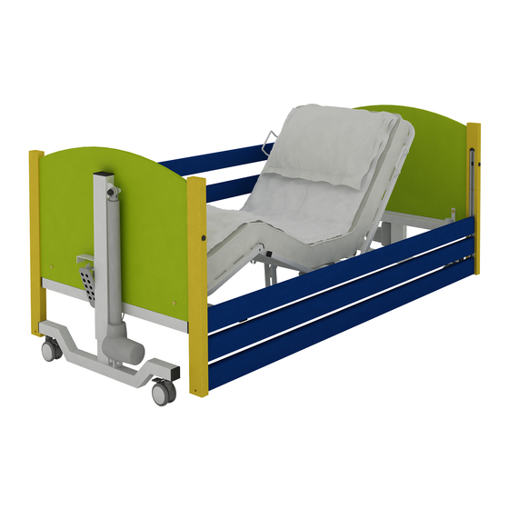
5. P ARTS 5.1. P ARTS SPECIFICATION (The figure shows the Taurus Junior LOW bed with wooden side rails) 1. Head end (actuator with blue marker) 2. Side rail 3. Side rail channel 4. Backrest mattress platform 5. Leg section frame 6. -
Page 16: Bed Assembly And Preparing For Use
6. B ED ASSEMBLY AND PREPARING FOR USE 6.1. R EMOVAL FORM THE TRANSPORT STAND ▪ Before attempting to assemble the bed, ensure these instruction manual has been read and fully understood. ▪ Ensure a risk assessment in line with local health and safety policy is undertaken to ensure that staff are not put at risk when performing assembly activities. -
Page 17: Assembling The Bed
6.2. A SSEMBLING THE BED ▪ Fit the head bed end (blue marker on the actuator cable) sliding the spigots into the backrest mattress platform end and determine the position of the set screws. Do not fully tighten the screws! ▪... -
Page 18: Fitting Electrical System
6.3. F ITTING ELECTRICAL SYSTEM The bed is designed to be connected to a constant power supply. ▪ Before installation, check condition of power cable, handset cable, actuators' cables and batteries in the control box (if supplied) and make sure they are not damaged. -
Page 19: Power Cable
Breaking or damaging seals of actuators or the control box will void the warranty. 6.3.1. H OLDER ARRANGEMENTS ON POWER CABLE Taurus Junior bed is equipped with 6 additional cable holders that allow the power cable suspension under the surface of the mattress. The picture below shows the arrangement. -
Page 20: Fitting The Side Rails
▪ All cables must be suspended from the platform frame on dedicated brackets, to avoid rubbing and cannot touch the floor. ▪ Incorrect placement/deployment of the power cable may cause the damage or cut of the cable – this situation may expose live conductors (risk of electric shock). - Page 21 ▪ Now take three side rails (rounded face pointing upward) and slide the end of them into both sets of fingers that are still located in the channel at the head end of the bed. Carefully rest the unattached ends on the floor taking care to ensure that the other ends are sufficiently far into the fingers so that they will not fall out.
-
Page 22: Checking The Bed
If there is any doubt about the assembly of the side rails contact the provider of the equipment, incorrectly fitted side rails can lead to death. 6.5. C HECKING THE BED The bed is now fully assembled. Before the bed is put into use ensure the bed is correctly assembled: ▪... -
Page 23: Training
7. T RAINING Professional personnel should be appropriately familiarized with the functionality of the bed, its limitations and the target user group before use. The user’s ability to operate the handset in an independent manner should be determined in acceptance with the risk assessment. -
Page 24: First Use
8. F IRST USE Prior to using the bed for the first time the following risk assessment must be performed based on the status of the patient and their body. This assessment should include, but is not limited to: ▪ The possibility of patient entrapment ▪... -
Page 25: Preparing For Start
▪ Keep distance of min 15 cm from the walls. ▪ Make sure all cables are not under excessive tension. ▪ If the bed is being used in conjunction with a hoist ensure the under bed clearances are checked before lowering the bed to minimum height - Risk of frames clashing. -
Page 26: Brake System
8.4. S IDE RAILS AND MATTRESSES Taurus Junior bed comes as a standard with a full length side rails. Wooden rails extend over the entire length of the bed. 8.4.1. M ATTRESS THICKNESS ▪... -
Page 27: Electrical Operation
8.5. E LECTRICAL OPERATION Taurus Junior bed has been equipped with a 9-button easy to use handset. It is intended for use by both the patient and the caregiver. However the handset should be operated by the care person. During the operation of the bed position by the caregiver, make sure that the user is informed about the change in the position of the mattress platform. -
Page 28: Handset Location
recommended that the handset is removed from the bed. ▪ Before lowering the bed ensure nobody is in close proximity to the underside of the bedframe – Risk of crushing. ▪ Before lowering the bed ensure feet / limbs are kept away from the castor pedals / yellow corner posts - Risk of crushing. -
Page 29: 9- Button Handset Operation
8.5.2. 9- BUTTON HANDSET OPERATION Note: when the bed is in the tilt position, levelling the mattress platform is carried out through the adjustment of the mattress platform high, by lifting the platform upwards (maximum value) or lowering down (maximum value) – until the mattress platform is levelled. -
Page 30: Handset Lockout
8.5.3. H ANDSET LOCKOUT The handset is supplied with a lockout function which enables the care person to disable the handset with a mechanic key (attached to the bag with Instructions For Use) until the light is on / off. The use of the handset lock function depends on the caregiver’s decision. - Page 31 ▪ Lowering the lower leg section to the lowest position will automatically reset the ratchet’s setting. Setting the bed so that the leg section angle adjustment operates: ▪ Press the leg section button on the handset and raise the leg section (height not important).
-
Page 32: Assembly Onto The Transport Stand
9. A SSEMBLY ONTO THE TRANSPORT STAND ▪ Before attempting to assemble the bed onto the transport stand ensure these instructions have been read and fully understood. ▪ Ensure a risk assessment in line with local health and safety policy is undertaken to ensure that staff are not put at risk when performing assembly activities. - Page 33 ▪ Whilst supporting the bed end pull the platform half away and gently position both sections on the floor / against a wall. ▪ Repeat for the remaining half of the bed. Assembling onto the Stand ▪ Position both transport stand brackets onto one bed end, taking care to ensure the brackets are both orientated in the correct direction.
-
Page 34: Power Failures
10. P OWER FAILURES The bed does not have battery backup functionality. In the event of a power failure the bed will not function and will remain in the position that it was in prior to the loss of power. 10.1. -
Page 35: Decontamination
11. D ECONTAMINATION Infection control and routine cleaning must be carried out in accordance with the Infection Control Policy, the local infection control schedule or recommendations from the local regulatory authorities. ▪ Always disconnect the bed from the main power supply prior to cleaning. - Page 36 Note: If any of the stages stated above are omitted or combined it will reduce the effectiveness of the clean. Note: The use of neat bleach or similar surface cleaners is not recommended as damage may be caused to the cleaned surfaces. ▪...
-
Page 37: Maintenance
12. M AINTENANCE Only authorised service personnel or RehaBed service engineers should carry out repairs or service activities. The manufacturer is not liable for unauthorised repairs. Failure to observe the rule may result in the manufacturer’s warranty becoming void. Service activities may be performed by any trained person or service personnel. The bed must be serviced annually, as a minimum. -
Page 38: Service Life
12.2. S ERVICE LIFE The service life of the Taurus Junior bed is 10 years*, with the exception of the mattresses. On the basis that the bed and its associated accessories are serviced and maintained in acceptance with the information detailed in these instructions for use and the individual instructions provided with the accessory in question. -
Page 39: Faulty Finding
12.3. F AULTY FINDING Listed below are a set of electrical faults that may occur within the service life of the bed. If a fault does occur please try the following suggestions, as these may help in diagnosing the fault, or contact the service department. Fault Possible cause Remedy... -
Page 40: Disposal Of Parts
13. D ISPOSAL OF PARTS When the bed frame / electrical system has come to the end of its useful life follow local recycling and W.E.E.E. (Waste Electrical and Electronic Equipment) policies. The electrical system on the bed frame is not to be disposed of in general municipal waste. -
Page 41: Electromagnetic Compatibility (Emc)
14. E (EMC) LECTROMAGNETIC COMPATIBILITY The electrical system has been designed to meet the necessary EMC requirements (IEC 60601-1-2 standard) however it may still be affected by or emit harmful radio frequency (RF) energy. The RF emissions from the electrical system are very low and are not likely to cause any interference to nearby electronic equipment, however interference to sensitive equipment is still possible. -
Page 42: Specification
15.3. T ECHNICAL DATA OF SIDE RAILS Taurus Junior bed has been tested and approved with wooden side rails along the entire length of the mattress platform. The table below presents the basic dimensions of side rails that can be used with the bed. - Page 43 The manufacturer recommends the use (only) the manufacturer’s side rails along with their beds. The manufacturer does not recommend the use of Taurus Junior bed with side rails for patients with a height of less than 125 cm – the equipment supplier is responsible for ensuring the suitability for use.
-
Page 44: Electrical Data
15.4. E LECTRICAL DATA Power supply plug Control unit Voltage in: 100 - 240V, 50/60Hz 24-29V DC Current in: 2A max 8A max Standby power: ≤ 0.5W Electric shock protection: Class II Class III Duty cycle:* 2 mins of continuous use followed by 18 mins not in use. 5 switching cycles per one minute *Electrically operated beds are intended to be operated intermittently rather than continuously. -
Page 45: Accessories
16. A CCESSORIES The Taurus Junior bed has been tested and approved with the following accessories: ▪ Lifting pole with plastic handgrip ▪ Medical mattress 780mm x 1900mm Characteristics of the accessories can be found in the relevant accessory’s instructions for use. -
Page 46: Lifting Pole
▪ The manufacturer deems the listed above foam mattresses to be suitable for use with the Taurus Junior side rail, however a patient risk assessment must be performed to ensure the gap between the top of the mattress and top of the side rail when fully lowered is acceptable and will not introduce a hazard to the patient when entering/exiting the bed. - Page 47 ▪ Installation of the lifting pole in a place that is not intended for this purpose poses a risk of damage to health or an accident. ▪ In order to ensure the user’s safety while using the lifting pole, make sure that the lifting pole has been properly installed.
-
Page 48: Warranty
17. W ARRANTY The warranty period is 24 months from the date of purchase of the bed. This warranty does not cover mechanical damage and interference in the structure, actuators and control box of the bed. In the absence of regular maintenance, the guarantor is not liable for resulting damage. - Page 49 The product supplied for repair is not complete, Failure to adhere with cautions and warnings in the instruction manual. 13. Consideration of the claim applies only to products placed on the market by the Manufacturer RehaBed sp. z o. o.
-
Page 50: Repairs And Servicing
18. R EPAIRS AND SERVICING ERVICING COMPANY ESCRIPTION SIGNATURE AND SEAL... -
Page 51: Remarks And Notes
19. R EMARKS AND NOTES... - Page 52 INSTRUC/TR-JUNIOR/EN, 2021/04 REV5...
Need help?
Do you have a question about the Taurus Junior and is the answer not in the manual?
Questions and answers