Table of Contents
Advertisement
Quick Links
Advertisement
Table of Contents

Related Manuals for Rehabed LEO


Summary of Contents for Rehabed LEO
-
Page 3: Table Of Contents
8.5.1. S ..... 28 CONTENTS IDE RAIL SAFETY 8.5.2. M ....28 ATTRESS THICKNESS 8.5.3. O PERATING THE WOODEN FULL 1. INTRODUCTION ........4 .......... 29 LENGTH SIDE RAILS 1.1. C ........... 4 ONTACT 8.5.4. O PERATING THE IGHT SIDE RAILS 1.2. -
Page 4: Introduction
1.2. T O WHAT IT CONCERNS This instruction manual applies to Leo beds consisting of 4-section mattress platform with metal slats and electrically operated backrest and knee break. All products are CE marked – in accordance with the EC Directive on med ical devices (2017/745 (MDR)). -
Page 5: Use
1.4. U The Leo bed with scissor-pantograph mechanism has been designed to provide the user with optimal independence and freedom whilst aiding the manual handling requirements of the carer. The Leo bed with a 9-button handset (Trendelenburg position locked-off) is intended for use within domestic environment. -
Page 6: Contraindications
Make sure the product is suitable for your condition or dysfunction. 1.5. C ONTRAINDICATIONS The contraindications for using the Leo bed include: ▪ Cervical or skeletal traction, ▪ Unstable fractures of the spine – if the bed’s functions remain unlocked, ▪... -
Page 7: Warnings And Cautions
2. W ARNINGS AND CAUTIONS Warnings in this instruction manual indicate potential hazards, disregard of which could lead to injury or death. Cautions in this instruction manual identify potential hazards, disregard of which could result in damage to the equipment. 2.1. - Page 8 ▪ During assembly / disassembly and regular operation, particular attention should be paid to the risk of hand injury. ▪ Start and use of the defective device that could pose a risk to patients or others is forbidden. ▪ Actuators should not be used in the presence of flammable gases.
- Page 9 ▪ The bed should be in the lowest position if the patient is left unattended, in order to minimize the risk of injury caused by a fall. ▪ A handset must be locked if the patient should not change the height and/or tilt of the back and/or leg sections, or when there are doubts concerning the patient’s ability to safety control the functions of the bed.
- Page 10 ▪ During the adjustment and maintenance attention should be paid to ensure that no part of the body is found in the potentially hazardous section (movable: backrest section, leg section, high / low system, side rails) - risk of injury to the limbs! ▪...
-
Page 11: Transport And Storage
3. T RANSPORT AND STORAGE The following conditions should be followed when transporting and storing the bed: ▪ Bed always to be stored on a flat and level floor. ▪ Bed ends set to minimum height. ▪ Side rail components (not including wooden side rails) to be kept in the aluminum channels on the bed ends (or stored safely together). - Page 12 ▪ If the bed is removed from its place of use by the end user, before handing the bed over for storage, make sure that the bed has been cleaned and disinfected – in acceptance with your local infection control rules and/or rules that are specified in this instruction manual (see section 11).
-
Page 13: Symbol Definitions
4. S YMBOL DEFINITIONS The following symbols are observed on the beds: Warning Beware of potential hazard Cautions Beware of potential hazard Refer to instructions for use – recommended Failure to read the instructions for use could introduce a hazard Refer to instructions for use –... - Page 14 Warning – dynamic mattress Dynamic mattresses must only be strapped to moving parts of bed frame Electrical specification Including storage and use conditions Warning – removable side rail Incompatible and improperly installed side rails may pose a risk of injury or death - see the instruction manual Total product weight in transport mode Heavy weight of the product - be careful when transporting on the transport stand and...
-
Page 15: Parts
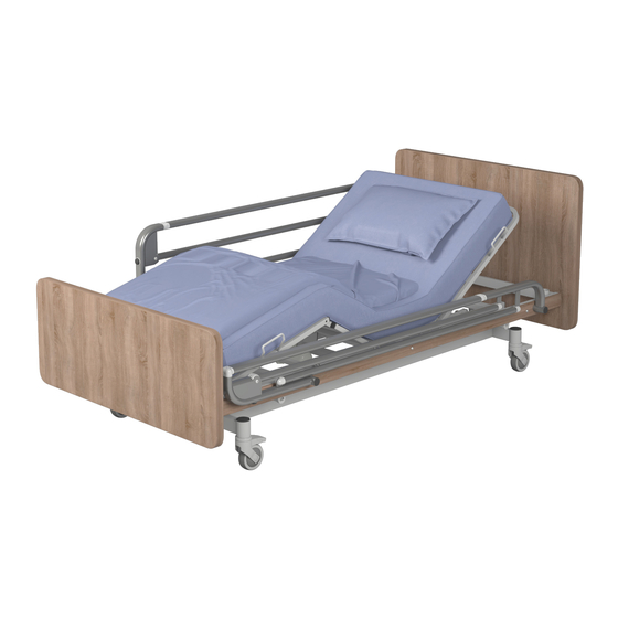
5. P ARTS 5.1. P ARTS SPECIFICATION (The figure shows the Leo bed with wooden side rails) 1. Head end 2. Side rail 3. Side rail channel (aluminum channel) 4. High / Low actuator 5. Backrest mattress platform 6. Backrest section actuator and control box 7. -
Page 16: Bed Assembly And Preparing For Use
6. B ED ASSEMBLY AND PREPARING FOR USE ▪ Before attempting to assemble the bed, ensure these instruction manual has been read and fully understood. ▪ Ensure a risk assessment in line with local health and safety policy is undertaken to ensure that staff are not put at risk when performing assembly activities. - Page 17 ▪ Check condition of power cable, handset cable and actuators' cables and make sure they are not damaged. ▪ Once all the cables are connected they are to be secured in place by attaching the retaining clip. Note: Actuator and handset cables are not shown (Image courtesy of DewertOkin GmbH) ▪...
-
Page 18: Power Cable
6.1.1. H OLDER ARRANGEMENTS ON POWER CABLE Leo bed is equipped with 7 additional cable holders that allow the power cable suspension under the mattress platform. The figure below presents the arrangement. ▪ All cables must be suspended from the platform frame on dedicated brackets, to avoid rubbing and cannot touch the floor. -
Page 19: Fitting The Wooden , Full - Length Side Rails
6.3. F ITTING THE WOODEN FULL LENGTH SIDE RAILS Before installation, make sure that the length of side rails is suitable for the length of the mattress’s platform (see section 15.3). ▪ Lower/raise the bed to its medium height (see section 8.6.2 regarding the operation of the bed’s electrical functions). -
Page 20: Fitting The Light Side Rails
6.5. F ITTING THE SPLIT SIDE RAILS The Leo bed is delivered with fitted split side rails. The following instructions may be helpful when you need to replace the side rails or their components. - Page 21 ▪ Prepare the dome head screws and the Ericson nuts. ▪ Place the Ericson nuts in the holes from the inside of the mattress platform (3 pcs.) in the place where the side rail will be fitted. ▪ Prepare a side rail and place it on the mattress platform.
-
Page 22: Checking The Bed
6.6. C HECKING THE BED The bed is now fully assembled. Before the bed is put into use ensure the bed is correctly assembled: ▪ Ensure the correct side rails are fitted to the bed, refer to section 15.3. ▪ Are the set and dome screws on all 4 corners of the bed fully tightened? ▪... -
Page 23: Training
7. T RAINING Professional personnel should be appropriately familiarized with the functionality of the bed, its limitations and the target user group before use. The user’s ability to operate the handset in an independent manner should be determined in acceptance with the risk assessment. -
Page 24: First Use
8. F IRST USE Prior to using the bed for the first time the following risk assessment must be performed based on the status of the patient and their body. This assessment should include, but is not limited to: ▪ The possibility of patient entrapment ▪... -
Page 25: General Safety
8.2. G ENERAL SAFETY ▪ When the bed is operated, make sure that objects such as a bedside table or other furniture are not an obstacle. ▪ Before exploiting the bed, make sure that the patient has been positioned correctly. ▪... -
Page 26: Brake System
8.4. B RAKE SYSTEM The LEO bed can be equipped with a castors with individual lock, axle lock or central lock (optionally with a direction lock). For safety reasons, wheels should be blocked with the foot (not with the use of a hand), and the manufacturer recommends wearing adequate footwear. -
Page 27: Castors With Individual Lock
8.5. S IDE RAILS AND MATTRESSES Leo bed comes as a standard with a full length side rails. Wooden rails extend over the entire length of the bed. Additionally, you can order a height extension to wooden rails. -
Page 28: Side Rail Safety
Manufacturer only recommends the use of manufacturers side rails with this bed. Manufacturer does not recommend the use of the Leo bed and side rails when caring for individuals who are less than 146cm in length - It is the equipment provider’s responsibility to ensure suitability for use. -
Page 29: Length Side Rails
8.5.3. O PERATING THE WOODEN FULL LENGTH SIDE RAILS To lower side rails: ▪ Lift the side rails gently, vertically upwards. ▪ Press the release button for side rails. ▪ Gently lower the side rails (the release button can be let depressed when lowering side rails). -
Page 30: Electrical Operation
8.6. E LECTRICAL OPERATION Leo bed has been equipped with a 9-button or 10-button easy-to-use handset. It is intended for use by both the patient and the caregiver. However the handset should be operated by the care person. During the operation of the bed position by the caregiver, make sure that the user is informed about the change in the position of the mattress platform. -
Page 31: Handset Location
▪ Ensure a risk assessment is undertaken to ensure the suitability of the occupant or visitor using the handset. ▪ The handset cable must also be considered in regards to the risk of accidental strangulation of the bed occupant or visitors –... -
Page 32: And 9- Button Handset Operation
The manufacturer recommend that the handset is positioned on the side rails with all functions locked out when the patient is left unattended to minimise the risk of unauthorsied operation and accidental strangulation. 8.6.2. 10 BUTTON HANDSET OPERATION Note: when the bed is in the tilt position (even if the Trendelenburg function is locked), levelling the mattress platform is carried out through the adjustment of the mattress platform high, by lifting the platform upwards (maximum value) or lowering down (maximum value) –... -
Page 33: Handset Lockout
▪ Consideration is to be taken in the location of the handset lockout key to minimise the risk of unauthorised users changing the lock setting. ▪ If patient requirements are such that Trendelenburg functionality is still deemed to pose a potential risk a replacement handset purchased... - Page 34 Setting the bed so that the leg section height adjustment operates: ▪ Press the leg section button on the handset and raise to maximum height. ▪ Lift the leg section manually with the use of handles so that the ratchet engages (once engaged the leg section will be supported by the ratchet).
-
Page 35: Disassembling The Bed For Transport
9. D ISASSEMBLING THE BED FOR TRANSPORT ▪ Before attempting to disassemble the bed ensure these instructions have been read and fully understood. ▪ Ensure a risk assessment in line with local health and safety policy is undertaken to ensure that staff are not put at risk when performing disassembly activities. - Page 36 ▪ Make sure that moving parts were secured with cable ties, stretch foil (etc.) – the risk of uncontrolled movements of individual sections during transport. ▪ During transport hold only the constant parts of bed construction.
-
Page 37: Power Failures
10. P OWER FAILURES The bed can be equipped (optionally) with additional emergency power supply – Backup System, that enable to lower the backrest and leg sections in the event of a power failure. If the bed is not equipped with an auxiliary power supply, in the event of a power failure, the electrical functions will not work. - Page 38 ▪ If the section should be lowered while the patient is in the bed, a risk assessment consistent with local health and safety regulations ought to be carried out in order to determine if it is possible to levelled the section with the load in a safe way. ▪...
-
Page 39: Decontamination
11. D ECONTAMINATION Infection control and routine cleaning must be carried out in accordance with the Infection Control Policy, the local infection control schedule or recommendations from the local regulatory authorities. ▪ Always disconnect the bed from the main power supply prior to cleaning. - Page 40 Note: If any of the stages stated above are omitted or combined it will reduce the effectiveness of the clean. Note: The use of neat bleach or similar surface cleaners is not recommended as damage may be caused to the cleaned surfaces. ▪...
-
Page 41: Maintenance
12. M AINTENANCE Only authorised service personnel or Reha-Bed sp. z o.o. service engineers should carry out repairs or service activities. The manufacturer is not liable for unauthorised repairs. Failure to observe the rule may result in the manufacturer’s warranty becoming void. - Page 42 ▪ Only manufacturer approved components, specified for the Leo bed, should be used - if in doubt contact your local distributor, importer or manufacturer. ▪ Never attempt to re-wire any components. ▪ Over time, the auxiliary emergency power supply may emit an increased amount of flammable gas, creating a risk of explosion/fire.
-
Page 43: Service Life
12.2. S ERVICE LIFE The service life of the Leo bed is 10 years*, with the exception of the mattresses. On the basis that the bed and its associated accessories are serviced and maintained in acceptance with the information detailed in these instructions for use and the individual instructions provided with the accessory in question. -
Page 44: Faulty Finding
12.3. F AULTY FINDING Listed below are a set of electrical faults that may occur within the service life of the bed. If a fault does occur please try the following suggestions, as these may help in diagnosing the fault, or contact the service department. Fault Possible cause Remedy... -
Page 45: Disposal Of Parts
13. D ISPOSAL OF PARTS When the bed frame / electrical system has come to the end of its useful life follow local recycling and W.E.E.E. (Waste Electrical and Electronic Equipment) policies. The electrical system on the bed frame is not to be disposed of in general municipal waste. -
Page 46: Electromagnetic Compatibility (Emc)
14. E (EMC) LECTROMAGNETIC COMPATIBILITY The electrical system has been designed to meet the necessary EMC requirements (IEC 60601-1-2 standard) however it may still be affected by or emit harmful radio frequency (RF) energy. The RF emissions from the electrical system are very low and are not likely to cause any interference to nearby electronic equipment, however interference to sensitive equipment is still possible. -
Page 47: Specification
15. S PECIFICATION 15.1. B ED DATA with with Leo L Leo S Leo M integrated Wide length extension Overall length [mm] 2060 2060 2060 2075 2060/2260 Overall width [mm] 1050 1070 1070 1270 1070 Mattress platform height range [mm]... -
Page 48: Technical Data Of Side Rails
15.3. T ECHNICAL DATA OF SIDE RAILS Leo bed has been tested and approved with wooden side rails along the entire length of the mattress platform, the Light side rails and the split side rails. The table below presents the basic dimensions of side rails that can be used with the bed. -
Page 49: Electrical Data
15.4. E LECTRICAL DATA MCL II control box Voltage in: 100 – 240V, 50/60 Hz Current in: Max. 3,15A Electric shock protection: Class II Duty cycle:* 2 mins of continuous use followed by 18 mins not in use 5 switching cycles per minute *Electrically operated beds are intended to be operated intermittently rather than continuously. -
Page 50: Accessories
16. A CCESSORIES The Leo bed has been tested and approved with the following accessories: LEO L LEO M LEO S ✓ ✓ ✓ Lifting pole with plastic handgrip extension (+mattress ✓ ✓ extension)* Bed extension with wooden slat ✓... -
Page 51: Mattress And Side Rails
16.1. M ATTRESS AND SIDE RAILS Leo bed has been tested and approved with listed below mattresses. The mattresses listed below are mattresses recommended by the manufacturer. Contact your distributor, importer or manufacturer to select a mattress suitable for your bed. - Page 52 ▪ The manufacturer deems the listed above foam mattresses to be suitable for use with the Leo side rail, however a patient risk assessment must be performed to ensure the gap between the top of the mattress and top of the side rail when fully lowered is acceptable and will not introduce a hazard to the patient when entering/exiting the bed.
-
Page 53: Lifting Pole
17. L IFTING POLE Optionally, the bed can be equipped with a lifting pole with a triangular handle with an adjustable length of the belt. In order to install the lifting pole: ▪ Lock all 4 wheels. ▪ Select one of the two lifting pole sockets located at the corners of the mattress platform (on the head bed end). -
Page 54: Warranty
18. W ARRANTY The warranty period is 24 months from the date of purchase of the bed. The warranty does not cover mechanical damage and interference with the bed’s structure, actuators or the bed’s control box. In the absence of regular inspections, the guarantor is not responsible for any damage resulting from this fact. - Page 55 a) It is not possible to identify the product from the serial number and production date on the bed. b) The product has been used in a manner inconsistent with the manner described in the instruction manual. The product has been used for other purposes or in conditions other than the intended ones.
- Page 56 INSTRUC/LEO/EN, 2021/04 REV2...
Need help?
Do you have a question about the LEO and is the answer not in the manual?
Questions and answers