Table of Contents
Advertisement
Quick Links
Advertisement
Table of Contents

Related Manuals for Rehabed TAURUS


Summary of Contents for Rehabed TAURUS
-
Page 3: Table Of Contents
8.5. E ......32 Table of contents LECTRICAL CONTROL 8.5.1. L ..33 OCATION OF THE HANDSET 8.5.2. O 1. INTRODUCTION ........4 PERATION OF BUTTON AND ......... 33 BUTTON HANDSETS 1.1. C ........... 4 ONTACT 8.5.3. L 1.2. W OCK FUNCTION OF THE HANDSET HAT THE INSTRUCTION MANUAL IS .............. -
Page 4: Introduction
1.2. W HAT THE INSTRUCTION MANUAL IS ABOUT This instruction manual applies to Taurus and Bariatric beds with the possibility of electric control of the back and leg sections. All products are CE marked – in accordance with the EC Directive on medical devices... -
Page 5: General Information
BMI greater than 17 and a maximum weight up to 178 kg (for the Taurus bed) or 318 kg (for the Bariatric bed). The lower (or upper) age limit is not defined. The usability of the bed depends on the physical size of the patient in relation to the various proportions and spaces around the bed’s frame. -
Page 6: Contraindications
Make sure the product is suitable for your condition or dysfunction. 1.5. C ONTRAINDICATIONS The contraindications for using the Taurus or Bariatric bed include: ▪ Cervical or skeletal traction, ▪ Unstable fractures of the spine – if the bed’s functions remain unlocked, ▪... -
Page 7: Warnings And Cautions
2. W ARNINGS AND CAUTIONS Warnings in this instruction manual indicate potential hazards, disregard of which could lead to injury or death. Cautions in this instruction manual identify potential hazards, disregard of which could result in damage to the equipment. 2.1. - Page 8 ▪ If the product is connected to the power supply with an extension cable, never overload the product by connecting devices that exceed the maximum rating of the extension cable – risk of fire. ▪ Make sure that there are not many sockets under the frame – liquids that may seep into such a socket during normal use of the bed may pose electrical/fire hazard.
- Page 9 150 mm. ▪ The height extension of the side rails enables to use mattresses with a maximum height of 330 mm (Taurus beds) and 350 mm (Bariatric beds). ▪ The use of accessories that have not been designed for use with the bed is forbidden.
- Page 10 ▪ In order to enable the disconnection of the bed from the mains, ensure that the plug is accessible. ▪ Due to the small space under the bed, special attention should be paid to young children, user limbs and other items around the bed that could be trapped between the bed’s components and injured or damaged.
-
Page 11: Transport And Storage
3. T RANSPORT AND STORAGE Observe the following instructions when transporting and storing the bed: ▪ Store the bed on the transport stand to save space. ▪ Always store the bed on a flat, level surface. ▪ Set the bed to the minimum height. ▪... - Page 12 ▪ In order to prevent the risk of cross contamination, when removing the bed from its place of use by the end user, make sure that all actions (connected with the bed) are carried out with the use of disposable gloves. Next to, properly dispose the glove, unless it can be verified that the bed and all accessories have been properly disinfected and cleaned.
- Page 13 ▪ Take special precautions concerning EMC. The bed should be installed and put into operation in a manner described in chapter 14. ▪ The bed with an additional source of emergency power supply is not intended to discharge batteries for a long time and it should always be connected to the power supply during normal use –...
-
Page 14: Symbols And Markings
4. S YMBOLS AND MARKINGS The following symbols are observed on the beds: Warning Warning of the potential risk Caution Warning of potential damage to the product Reference to the instruction manual - recommended Failure to comply with the recommendation may cause a risk Reference to the instruction manual - mandatory Failure to comply with the recommendation may cause a risk Maximum user weight... - Page 15 Warning – dynamic mattress Dynamic mattresses must only be strapped to moving parts or bed’s frame Warning – specific height of side rails Required specific height of side rails (Bariatric beds) Electrical specification Including storage and use conditions Warning – removable side rail Incompatible and improperly installed side rails may pose a risk of injury or death - see the instruction manual Total product weight on the transport stand...
-
Page 16: Component Parts
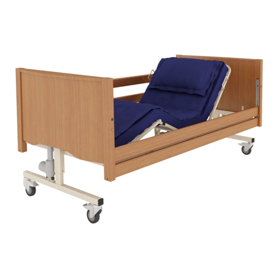
OMPONENT PARTS 5.1. L IST OF COMPONENTS OF THE BED (The figure shows the Taurus LOW LUX bed with wooden side rails) 1. Head bed end (actuator with blue marker) 2. Wooden side rails 3. Side rails channel (aluminium channel) 4. -
Page 17: Assembly Of The Bed And Preparation For Use
6. A SSEMBLY OF THE BED AND PREPARATION FOR USE 6.1. D ISASSEMBLY FROM THE TRANSPORT STAND ▪ Make sure that you have read and fully understood the instruction manual before the assembly of the bed. ▪ Make sure that a risk assessment has been conducted in acceptance with local health and safety regulations in order to protect personnel from risks during assembly works. -
Page 18: Assembly Of The Bed
6.2. A SSEMBLY OF THE BED ▪ Fit the head bed end (blue marker on the actuator’s cable) to the backrest mattress platform frame by inserting connectors into the end of the backrest section, and then locate the locking and set screws and gently tighten them. Do not tighten the screws! ▪... -
Page 19: Connection Of The Electrical System
Next to, connect the cables in acceptance with the colour scheme to the control box as shown in the picture below. The fitted cables should be secured against displacement with the use of the provided clip (plastic cover/plug). Connection diagram of the ECS system (TAURUS beds): White marker Blue marker... - Page 20 After connecting all cables, secure them against displacement with the use of the provided plug. Handset and actuator cables are not shown Make sure that the power cable from the control box and the power connector are properly connected. For this purpose, make sure that both ends have been properly Source: DewertOkin GmbH pressed.
- Page 21 ▪ Plug the power cable into the holder located on the lower part of the back section (Taurus beds only). ▪ Make sure that none of the actuator and/or handset cables are placed between moving parts of the bed and check that cables...
- Page 22 6.3.1. P LACEMENT OF POWER CABLE HOLDERS AND CABLE SCHEME The Taurus bed is equipped with six holders and the Bariatric bed is equipped with one holder that enable to suspend the power cable under the mattress platform. The figure below presents the position of holders.
-
Page 23: Assembly Of Wooden Side Rails
▪ Consider the adequate placement of actuator and/or handset cables in order to minimize the risk of accidental suffocation as a result of the entanglement of the user and/or other people. 6.4. A SSEMBLY OF WOODEN SIDE RAILS Before installation, make sure that the length of side rails is suitable for the length of the mattress’s platform (standard or extended side rails). - Page 24 ▪ While the top side rail is being held, insert the spacer into the aluminium channel, and then insert the top aluminium pin of the bottom slider into the lower hole of the lift wire. Next to, slide the end of the bottom side rail into the aluminium pins of the bottom slider and raise the side rails mechanism until you hear the sound of the side rail lock’s blockade.
-
Page 25: Checking The Bed
6.5. C HECKING THE BED The bed is fully assembled now. Before use, make sure it is assembled in a correct manner by answering the following questions: ▪ Ensure the correct side rails are fitted to the bed. ▪ Are the set screws and the locking screws in all 4 corners of the bed fully tightened? ▪... -
Page 26: Training
7. T RAINING Professional personnel should be appropriately familiarized with the functionality of the bed, its limitations and the target user group before use. The user’s ability to operate the handset in an independent manner should be determined in acceptance with the risk assessment. -
Page 27: First Use
The safe working load is 215 kg (for Taurus beds) and 368 kg (for Bariatric beds). The bed is equipped with 4 lockable wheels to allow manoeuvring the bed. However, the bed is not intended for transport of the patient. -
Page 28: General Safety
8.1. G ENERAL SAFETY ▪ Before using the bed, make sure that objects such as a bedside table or other furniture are not obstacles. ▪ Before using the bed, make sure that the user is correctly positioned. ▪ Before leaving the user without any supervision, make sure that the bed is set to the minimum height. -
Page 29: Brake System
▪ the handset’s functions are locked/unlocked (depending on the assessment of the patient’s condition and the environment – see section 8.5.3) ▪ the bed is placed horizontally on a flat surface so all the castors touch the ground. ▪ If electrical functions do not work properly, make sure that the handset is unlocked (see chapter 8.5.3). -
Page 30: Side Rails And Mattress
Wheels should be locked / unlocked by foot, not by hand. 8.4. S IDE RAILS AND MATTRESS Taurus and Bariatric beds are fitted with wooden side rails along the whole length of the bed (as the standard). Characteristics of the mattresses and the side rails tested and approved by the manufacturer can be found in the section 15.3. -
Page 31: Use Of Side Rails
▪ The use of side rails that have not been approved for use with the bed is unacceptable due to the risk of loss of health or life. 8.4.2. U SE OF SIDE RAILS To lower side rails: ▪ Gently lift the top side rail. ▪... -
Page 32: Electrical Control
8.5. E LECTRICAL CONTROL Taurus and Bariatric beds are equipped with a 9-button or 10-button easy-to-use handset. It is intended for use by both the patient and the caregiver. Thanks to the use of the handset, it is possible to control the electronic, linear system of actuators, which are controlled by the central control box. -
Page 33: Location Of The Handset
Using the bed without any breaks for a long period of time or exceeding the operating time of the control box and/or actuators may cause temporary shutdown or irreversible damage to the electrical system. In such a case, disconnect the power cable from the mains before using the device again. -
Page 34: Lock Function Of The Handset
Note: when the bed is in the tilt position (even if the Trendelenburg function is locked), levelling the mattress platform is carried out through the adjustment of the mattress platform high, by lifting the platform upwards (maximum value) or lowering down (maximum value) –... -
Page 35: Leg Section
To lock/unlock the Trendelenburg function with the use of a mechanical key (only in the case of 10-button handset): Turn the handset over, put the key in the recess on the back of the handset, turn the lock to the place indicated in the picture above. To lock/unlock the handset with the use of a magnetic key, slide the key over the handset –... - Page 36 Setting the bed so that the leg section angle adjustment operates: ▪ Raise the leg section to the selected height on the handset (the height is not important). ▪ Manually lift the leg section in order to disengage the ratchet (if in doubt lift the leg section to the ratchet’s maximum extent).
-
Page 37: Disassembling The Bed For Transport
9. D ISASSEMBLING THE BED FOR TRANSPORT ▪ Before attempting to disassemble the bed ensure these instructions have been read and fully understood. ▪ Ensure a risk assessment in line with local health and safety policy is undertaken to ensure that staff are not put at risk when performing disassembly activities. - Page 38 ▪ Unscrew set screws and dome screws located at mattress platform near to one of bed ends. ▪ Holding the bed ends, slide out half of the mattress platform and gently lay both parts on the floor or lean against the wall. ▪...
-
Page 39: Power Failures
10. P OWER FAILURES Depending on the type of control box, the bed can be equipped (optionally) with additional emergency power supply – Backup System (MCL II) or Emergency Low System (ECS) that enable to lower the backrest and leg sections in the event of a power failure. - Page 40 ▪ Remove the retaining pin and the clevis pin holding the actuators piston in place (only on one side!). ▪ Remove the piston by placing it gently on the floor – it can hang down. ▪ Gently lower the section to the horizontal position. ▪...
-
Page 41: Decontamination
11. D ECONTAMINATION Infection control and routine cleaning should be carried out in acceptance with the local infection control schedule or recommendations from the local regulatory authorities. ▪ Always disconnect the bed from the main power supply prior to cleaning. ▪... - Page 42 Note: If any of the stages stated above are omitted or combined it will reduce the effectiveness of the clean. Note: The use of neat bleach or similar surface cleaners is not recommended as damage may be caused to the cleaned surfaces. ▪...
-
Page 43: Maintenance And Inspections
12. M AINTENANCE AND INSPECTIONS Only authorized service personnel and employees of Reha-Bed Sp. z o.o. are entitled to repair the bed or interfere with its structure. Reha-Bed Sp. z o.o. is not responsible for repairs carried out by unauthorized service technicians. Failure to observe the rule may result in the manufacturer’s warranty becoming void. - Page 44 ▪ Only manufacturer approved components (for Taurus and Bariatric beds) can be used – if in doubt contact the manufacturer or your local distributor. ▪ Attempts to change the wiring of any bed components are strictly forbidden. ▪ Over time, the auxiliary emergency power supply may emit an increased amount of flammable gas –...
-
Page 45: Service Life
12.2. S ERVICE LIFE The service life of the Taurus and Bariatric range beds is 10 years*, with the exception of the emergency power systems and the mattresses. On the basis that the bed and its associated accessories are serviced and maintained in acceptance with the information detailed in these instructions for use and the individual instructions provided with the accessory in question. -
Page 46: Fault Finding
12.3. F AULT FINDING The most common failures/operating errors that may occur while using the bed are described below. In the event of any fault, use the instructions below that may help you to diagnose the fault or contact the service department. Description of Possible cause Remedy... -
Page 47: Disposal Of Parts
13. D ISPOSAL OF PARTS When the bed frame / electrical system has come to the end of its useful life follow local recycling and W.E.E.E. (Waste Electrical and Electronic Equipment) policies. The electrical system on the bed frame is not to be disposed of in general municipal waste. -
Page 48: Electromagnetic Compatibility (Emc)
14. E (EMC) LECTROMAGNETIC COMPATIBILITY The electrical system has been designed to meet the necessary EMC requirements (PN- EN 60601-1-2 standard) however it may still be affected by or emit harmful radio frequency (RF) energy. The RF emissions from the electrical system are very low and are not likely to cause any interference to nearby electronic equipment, however interference to sensitive equipment is still possible. -
Page 49: Specification
15. S PECIFICATION 15.1. T ECHNICAL DATA OF THE BED TAURUS TAURUS TAURUS TAURUS TAURUS TAURUS TAURUS SILVER SILVER LOW LUX LOW LUX Overall length 2180 mm 2230 mm 2230 mm 2180 mm 2230 mm 2230 mm 2180 mm Overall width... - Page 50 TAURUS TAURUS TAURUS TAURUS TAURUS TAURUS MINI MINI MINI MINI LUX MINI LUX MINI LUX 900x1900 780x2000 780x1900 900x1900 780x2000 780x1900 Overall length 2080 mm 2180 mm 2080 mm 2120 mm 2230 mm 2120 mm Overall width 1050 mm 930 mm...
-
Page 51: Maximum Load
Trendelenburg function removed – for details contact with your local distributor or the manufacturer 15.2. M AXIMUM LOAD TAURUS BARIATRIC LIFTING POLE Safe working load 215 kg 368 kg... -
Page 52: Technical Data Of Side Rails
15.3. T ECHNICAL DATA OF SIDE RAILS Taurus and Bariatric beds have been tested and approved with wooden side rails along the entire length of the mattress platform. The table below presents the basic dimensions of side rails that can be used with selected beds. -
Page 53: Electrical Data
15.4. E LECTRICAL DATA Power plug MCL II control box ECS control box Voltage in: 100 - 240V, 50/60Hz 100 – 240V, 50/60Hz 24-29V Current in: max. 2A Max. 3,15A max. 8A Standby power: ≤ 0.5W Electric shock protection: Class II Class II Class II Duty cycle:*... -
Page 54: Accessories
16. A CCESSORIES Taurus and Bariatric beds have been tested and approved with the following accessories: TAURUS BARIATRIC ✓ Lifting pole with a handle ✓ Reinforced lifting pole with a handle Bed extension of Taurus bed mattress ✓ platform (+mattress extension)* Bed extension of Bariatric bed mattress ✓... -
Page 55: Mattress And Side Rails
16.1. M ATTRESS AND SIDE RAILS Taurus and Bariatric beds have been tested and approved with selected mattresses. The mattresses listed in the table below are mattresses recommended by the manufacturer. Contact the manufacturer or distributor to select a mattress suitable for your bed. - Page 56 900x1900x120; 900x2000x100; 900x2000x120; 900x2000x120; 900x2000x150; 1200x2000x150 Waffle mattress 850x2000x140; Waffle mattress with HR 780x1870x120; 780x2000x120 850x2000x120; insert 900x2000x120; 900x2000x150; 1200x2000x120 780x1870x120; 780x2000x120; Foam mattress 800x2000x120; 850x2000x120; 900x1800x120; 900x1900x120; 900x2000x100; 900x2000x120; 900x2000x150; 900x2000x200; 1200x2000x120; 1200x2000x150; 1200x2200x150 Foam mattress 900x2000x120; 900x2000x150 Foam mattress with HR 900x2000x150 insert 780x200x120;...
-
Page 57: Lifting Pole
holders on sides of the mattress platform sections – an incorrect mattress may pose a risk of entrapment and/or fall of the patient. ▪ Make sure that side rails and mattress are correctly selected – incorrect selection of products may pose a risk of entrapment. ▪... - Page 58 ▪ Installation of the lifting pole in a place that is not intended for this purpose poses a risk of damage to health or an accident. ▪ In order to ensure the user’s safety while using the lifting pole, make sure that the lifting pole has been properly installed.
-
Page 59: Warranty
17. W ARRANTY The warranty period is 24 months from the date of purchase of the bed. The warranty does not cover mechanical damage and interference with the bed’s structure, actuators or the bed’s control box. In the absence of regular inspections, the guarantor is not responsible for any damage resulting from this fact. - Page 60 a) It is not possible to identify the product from the serial number and production date on the bed. b) The product has been used in a manner inconsistent with the manner described in the instruction manual. The product has been used for other purposes or in conditions other than the intended ones.
-
Page 61: Repairs And Maintenance Treatments
18. R EPAIRS AND MAINTENANCE TREATMENTS SIGNATURE AND STAMP OF DATE DESCRIPTION THE SERVICE... -
Page 62: Notes
19. N OTES... - Page 64 INSTRUC/TR-BAR/EN, 2021/04 REV5...
Need help?
Do you have a question about the TAURUS and is the answer not in the manual?
Questions and answers