Table of Contents
Advertisement
Quick Links
Copyright
This publication, including all photographs, illustrations and software, is protected un-
der international copyright laws, with all rights reserved. Neither this manual, nor any
of the material contained herein, may be reproduced without written consent of the au-
thor.
Version 3.0
Disclaimer
The information in this document is subject to change without notice. The manufac-
turer makes no representations or warranties with respect to the contents hereof and
specifically disclaims any implied warranties of merchantability or fitness for any par-
ticular purpose. The manufacturer reserves the right to revise this publication and to
make changes from time to time in the content hereof without obligation of the manu-
facturer to notify any person of such revision or changes.
Trademark Recognition
Microsoft, MS-DOS and Windows are registered trademarks of Microsoft Corp.
MMX, Pentium, Pentium-II, Pentium-III, Celeron are registered trademarks of Intel
Corporation.
Other product names used in this manual are the properties of their respective owners
and are acknowledged.
Federal Communications Commission (FCC)
This equipment has been tested and found to comply with the limits for a Class B digi-
tal device, pursuant to Part 15 of the FCC Rules. These limits are designed to provide
reasonable protection against harmful interference in a residential installation. This
equipment generates, uses, and can radiate radio frequency energy and, if not in-
stalled and used in accordance with the instructions, may cause harmful interference
to radio communications. However, there is no guarantee that interference will not oc-
cur in a particular installation. If this equipment does cause harmful interference to
radio or television reception, which can be determined by turning the equipment off
and on, the user is encouraged to try to correct the interference by one or more of the
following measures:
−
Reorient or relocate the receiving antenna.
−
Increase the separation between the equipment and the receiver.
−
Connect the equipment onto an outlet on a circuit different from that to which
the receiver is connected.
−
Consult the dealer or an experienced radio/TV technician for help.
Shielded interconnect cables and a shielded AC power cable must be employed with
this equipment to ensure compliance with the pertinent RF emission limits governing
this device. Changes or modifications not expressly approved by the system's manu-
facturer could void the user's authority to operate the equipment.
Preface
Advertisement
Table of Contents

Related Manuals for ECS P6VEMT


Summary of Contents for ECS P6VEMT
- Page 1 Preface Copyright This publication, including all photographs, illustrations and software, is protected un- der international copyright laws, with all rights reserved. Neither this manual, nor any of the material contained herein, may be reproduced without written consent of the au- thor.
- Page 2 Declaration of Conformity This device complies with part 15 of the FCC rules. Operation is subject to the follow- ing conditions: − This device may not cause harmful interference, and − This device must accept any interference received, including interference that may cause undesired operation.
-
Page 3: Table Of Contents
Preface CHAPTER 1 Introducing the Mainboard Introduction ....................1 Checklist .....................1 Standard Items ....................1 Features .....................2 Choosing a Computer Case ...............4 Mainboard Components ................5 CHAPTER 2 Installing the Mainboard Safety Precautions..................7 Quick Guide ....................7 Installing the Mainboard in a Case..............8 Checking Jumper Settings ................8 Setting Jumpers .................... - Page 4 Integrated Peripherals ..................36 Power Management Setup ................39 PNP/PCI Configurations................42 PC Health Status.................... 44 Frequency Control ..................45 Load Optimized Defaults Option..............45 Set Supervisor and User Passwords Option........... 46 Save & Exit Setup Option ................46 Exit Without Saving ..................47 CHAPTER 4 Using the Mainboard Software About the Software CD-ROM ..............48...
-
Page 5: Introducing The Mainboard
The VT82C686B Southbridge chipset enhances the functionality of the stan- dard ISA peripherals. The P6VEMT is a micro-ATX board measuring 244 X 200 mm and using 4- layer printed circuit board. It also comes with a full set of I/O ports which in- cludes one serial port, a parallel port, a monitor port, a PS/2 mouse port, a PS/2 keyboard port, audio ports, USB ports and a game port. -
Page 6: Features
Processor The mainboard supports the Socket 370 which has the follow- ing features: • Accomodates Intel Pentium !!! processor, Tualatin proc- essor and VIA C3 processor • Supports 66/100/133 MHz CPU front-side bus (FSB) Chipset The VT8601T Northbridge and VT82C686B Southbridge chip- sets are based on a high compatibility and power efficient with proven reliability and performance. - Page 7 • One onboard LAN (optional) chip and LAN port on top of the USB port The P6VEMT supports Ultra DMA bus mastering with transfer rates of 33/66/100 MB/sec. Onboard LAN The Realtek RTL8100B is a highly integrated and cost- (optional) effective single-chip 10/100Mbps Fast Ethernet controller.
-
Page 8: Choosing A Computer Case
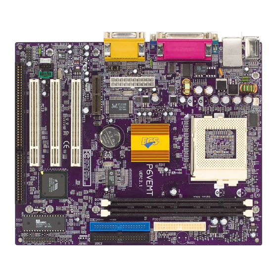
BIOS This mainboard uses Award BIOS that enables users to con- Firmware figure many system features including the following: • Power management • Wake-up alarms • CPU parameters and memory timing • CPU and memory timing The firmware can also be used to set parameters for different processor clock speeds. - Page 10 Table of Mainboard Components Label Component BAT1 Three volt realtime clock battery BIOS_WP1 BIOS Flash protect COM2 Onboard serial port connectors CPU Socket Socket 370 for PIII/C3 CPU_TEMP1* CPU Temperature Header DIMM1 ~ DIMM2 Two 184-pin DDR sockets FDD1 Floppy disk drive connector IDE1 Primary IDE channel IDE2...
-
Page 11: Installing The Mainboard
Installing the Mainboard Follow these safety precautions when installing the mainboard: • Wear a grounding strap attached to a grounded device to avoid damage from static electricity. • Discharge static electricity by touching the metal case of a safely grounded object before working on the mainboard. •... -
Page 12: Installing The Mainboard In A Case
Refer to the following illustration and instructions for installing the mainboard in a case: This illustration shows an ex- 2. Secure the mainboard with ample of a mainboard being screws where appropriate. installed in a tower-type case: Note: Do not overtighten the screws as this can stress the main- board. -
Page 13: Checking Jumper Settings
Checking Jumper Settings The following illustration shows the location of the mainboard jumpers. Pin 1 is labeled. Jumper Settings Jumper Description Setting (default) JCMOS1 Clear CMOS 1-2: Clear CMOS JCMOS1 jumper 2-3: Normal BIOS_WP1 BIOS Flash 1-2: Write Enabled BIOS_WP1 protect 2-3: Write Disabled JCMOS1 –... -
Page 14: Connecting Case Components
After you have installed the mainboard into a case, you can begin connecting the mainboard components. Refer to the following: Connect the case power supply connector to JATXPWR1. Connect the CPU cooling fan cable to JCFAN1. Connect the case cooling fan connector to JSFAN1. -
Page 15: Front Panel Connector
CPUTEMP1: CPU Temperature Header (for OEM customers only) Signal Name TempP+ TempN- Ground Note: Please use 0-ohm resistance to connect the pin 1 & 2 to the temperature reader chip. Front Panel Connector The panel connector (JPANEL1 and LPANEL1) provides a standard set of switch and LED connectors commonly found on ATX or micro-ATX cases. - Page 16 Speaker Connector An offboard speaker can be installed on the mainboard as a manufacturing option. An offboard speaker can be connected to the mainboard at the front panel connector. The speaker (onboard or offboard) provides error beep code information during the Power On Self-Test when the computer cannot use the video interface.
-
Page 17: Installing Hardware
Installing the Processor Caution: When installing a CPU heatsink and cooling fan make sure that you DO NOT scratch the mainboard or any of the surface-mount resistors with the clip of the cooling fan. If the clip of the cooling fan scrapes across the mainboard, you may cause serious damage to the mainboard or its components. - Page 18 CPU Installation Procedure The following illustration shows CPU installation components: Note: The pin-1 corner is marked with an arrow Follow these instructions to install the CPU: Pull the lever sideways away from the socket then raise the lever up to a 90- degree angle.
-
Page 19: Installing Memory Modules
Installing Memory Modules This mainboard accommodates two 168-pin 3.3V unbuffered SDRAM memory modules. You must install at least one module in any of the slots. Each mod- ule can be installed with 32 MB to 512 MB of memory; total memory capacity is 1GB. -
Page 20: Installing A Hard Disk Drive/Cd-Rom
Installing a Hard Disk Drive/CD-ROM This section describes how to install IDE devices such as a hard disk drive and a CD-ROM drive. About IDE Devices Your mainboard has a primary and secondary IDE channel interface (IDE1 and IDE2). An IDE ribbon cable supporting two IDE devices is bundled with the main- board. -
Page 21: Installing A Floppy Diskette Drive
Installing a CD-ROM/DVD Drive Install the CD-ROM/DVD drive into the drive cage in your system case. Plug the IDE cable into IDE1 (A). If you have already installed an HDD, use the other connec- tor on the IDE cable. Note: Ribbon cable connectors are usually keyed so that they can only be installed correctly on the device connector. -
Page 22: Installing Add-On Cards
When you first start up your system, go immediately to the Setup Utility to configure the floppy diskette drives that you have installed. Installing Add-on Cards The slots in this mainboard are designed to hold expansion cards and connect them to the system bus. Expansion slots are a means of adding or enhancing the mainboard’s features and capabilities. - Page 23 Follow these instructions to install an add-on card: Remove a blanking plate from the system case corresponding to the slot you are going to use. Install the edge connector of the add-on card into the expansion slot. Ensure that the edge con- nector is correctly seated in the slot.
-
Page 24: Audio Subsystem
Audio Subsystem Refer to the following for information on connecting the mainboard’s audio devices: JCDIN1: CD-ROM Audio-In Header Signal Name Right Channel Input Ground Ground Left Channel Input JCDIN2: CD-ROM Audio-In Header Signal Name Left Channel Input Ground Right Channel Input Ground JTAD1: Telephony Audio Header Signal Name... - Page 25 JAUDIO1: Front Audio Header This header allows the user to install auxiliary front-oriented microphone and line-out ports for easier access. Signal Name Signal Name Mic In Ground Mic Power Audio Power RT Line Out RT Line Out Reserved LFT Line Out LFT Line Out LAUDIO1: Front Audio Header (for OEM customers only)
-
Page 26: Connecting Optional Devices
Connecting Optional Devices Refer to the following for information on connecting the mainboard’s optional devices: COM2: Onboard serial port connector Connect a serial port extension bracket to this header to add a second serial port to your system. Signal Name Function NDCDB Data carry detect... - Page 27 WOL1: Wake On LAN If you have installed a LAN card, use the cable provided with the card to plug into the mainboard WOL1 connector. This enables the Wake On LAN (WOL) feature. When your system is in a power-saving mode, any LAN signal auto- matically resumes the system.
- Page 28 Note: Please make sure that the USB cable has the same pin assignment as indi- cated above. A different pin assignment may cause damage or system hang-up. SIR1: Serial infrared port The mainboard supports a Serial Infrared data port. Infrared ports allow the wireless exchange of information between your computer and similarly equipped devices such as printers, laptops, Personal Digital Assistants (PDAs), and other computers.
-
Page 29: Connecting I/O Devices
The backplane of the mainboard has the following I/O ports: Parallel port (LPT1) Game port PS/2 port mouse PS/2 Serial port VGA port Microphone keyboard ports COM 1 Line-in Line-out PS/2 Mouse Use the upper PS/2 port to connect a PS/2 pointing device. Use the lower PS/2 port to connect a PS/2 keyboard. -
Page 30: External Connector Color Coding
External Connector Color Coding Many connectors now use standard colors as shown in the table below. Connector Color Analog VGA Blue Audio line-in Light blue Audio line-out Lime Digital monitor/flat panel White IEEE 1394 Grey Microphone Pink MIDI/game Gold Parallel Burgundy PS/2-compatible keyboard Purple... -
Page 31: Using Bios
Using BIOS The computer uses the latest Award BIOS with support for Windows Plug and Play. The CMOS chip on the mainboard contains the ROM setup instructions for configuring the mainboard BIOS. The BIOS (Basic Input and Output System) Setup Utility displays the system's configuration status and provides you with options to set system parameters. -
Page 32: Starting Setup
Starting Setup The BIOS is immediately activated when you first turn on the computer. The BIOS reads system configuration in CMOS RAM and begins the process of checking out the system and configuring it through the power-on self test (POST). When these preliminaries are finished, the BIOS seeks an operating system on one of the data storage devices (hard drive, floppy drive, etc.). -
Page 33: Updating The Bios
BIOS Navigation Keys The BIOS navigation keys are listed below: Function Up arrow Move to previous item. Down arrow Move to next item. Left arrow Move to the item on the left (menu bar) Right arrow Move to the item on the right (menu bar) Move enter Move to the item you desired PgUp key... -
Page 34: Using Bios
At the A:\ prompt, type the Flash Utility program name and press <Enter>. You see a screen similar to the following: FLASH MEMORY WRITER V7.33 (C) Award Software 1999 All Rights Reserved For (MAINBOARD NAME) DATE: 10/26/2000 Flash Type File Name to Program :____________________ Error Message Type the filename of the new BIOS in the “File Name to Program”... -
Page 35: Standard Cmos Features
Standard CMOS Features In the Standard CMOS menu you can set the system clock and calendar, re- cord disk drive parameters and the video subsystem type, and select the type of errors that stop the BIOS POST. Phoenix – AwardBIOS CMOS Setup Utility Standard CMOS Features Date (mm:dd:yy) Tue, Sep 25 2001... -
Page 36: Advanced Bios Setup
Halt On All Errors No Errors Select the situation in which you All, but Keyboard want the BIOS to stop the POST All, but Diskette process and notify you. All, but Disk/Key Displays the amount of conven- Base Memory tional memory detected during boot up. - Page 37 Shadow Control If you highlight the literal “Press Enter” next to the “Shadow Control” label and then press the enter key, it will take you to a submenu with the following op- tions: Video BIOS Shadow Determines whether video BIOS will be copied to RAM for faster execution.
- Page 38 Sets the delay time after the key is held down before it begins to repeat the keystroke. Typematic Delay (Msec) (250) This option will enable only individuals with passwords to bring the system online and/or to use the CMOS Setup Utility. System A password is required for the system to boot and is also required to access the Setup Utility.
-
Page 39: Advanced Chipset Setup
Advanced Chipset Setup The parameters in this screen are for system designers, service personnel, and technically competent users only. Do not reset these values unless you understand the consequences of your changes. Phoenix – AwardBIOS CMOS Setup Utility Advanced Chipset Setup Bank Interleave [Disabled] Item Help... -
Page 40: Integrated Peripherals
OnChipUSB (Enabled) This should be enabled if your system has a USB installed on the system board and you wish to use it. Even when so equipped, if you add a higher performance controller, you will need to disable this feature. USB Keyboard/Mouse Support (Disabled) Select Enabled if your system contains a Universal Serial Bus (USB) control- ler and you have an USB keyboard/mouse. - Page 41 the “Onchip IDE Control” label and then press the enter key, it will take you a submenu with the following options. OnChip IDE Channel0/1 (Enabled) The integrated peripheral controller contains an IDE interface with support for two IDE channels. Select Enabled to activate each chan- nel separately.
- Page 42 Enable or Disable the MOU-401 function. MPU-401 I/O Address (330-333H) Change the SoundBlaster Pro MPU-401 I/O address. Game Port (200-207H) (Enabled) Change the joystick connect port addresses. Init Display First (PCI Slot) This item allows you to decide to activate the PCI slot or on-chip VGA first. IDE HDD Block Mode (Enabled) Enable this field if your IDE hard drive supports block mode.
-
Page 43: Power Management Setup
duplex mode permits simultaneous two-direction transmission. Half-duplex mode permits transmission in one direction only at a time. Onboard Parallel Port (378/IRQ7) This item allows you to determine access onboard parallel port controller with which I/O address. Parallel Port Mode (SPP) Using Parallel Port as Enhanced Parallel Port. - Page 44 PC to be turned on and off by external devices, so that mouse or keyboard activity wakes up the computer. Power Management This item acts like a master switch for the power-saving modes and hard disk timeouts. If this item is set to Max Saving, power-saving modes occur after a short timeout.
- Page 45 power saving mode if there is any VGA activity. LPT & COM (LPT/COM ) When this item is enabled, the system will restart the power-saving timeout counters when any activity is detected on the serial ports, or the parallel port. HDD &...
-
Page 46: Pnp/Pci Configurations
Phoenix – AwardBIOS CMOS Setup Utility IRQs Activity Monitoring Item Help Primary INTR [ON] IRQ 3 (COM2) [Enabled] Menu Level IRQ 4 (COM1) [Enabled] IRQ 5 (LPT2) [Enabled] IRQ 6 (Floppy Disk) [Enabled] IRQ 7 (LPT1) [Enabled] IRQ 8 (RTC Alarm) [Disabled] IRQ 9 (IRQ2 Redir) - Page 47 ponent Interconnect) is a system, which allows I/O devices to operate at speeds nearing CPU’s when they communicate with own special components. All the options describes in this section are important and technical and it is strongly recommended that only experienced users should make any changes to the default settings.
-
Page 48: Pc Health Status
Some graphic controllers which are not VGA compatible take the output from a VGA controller and map it to their display as a way to provide boot informa- tion and VGA compatibility. However, the color information coming from the VGA controller is drawn from the palette table inside the VGA controller to generate the proper colors, and the graphic controller needs to know what is in the palette of the VGA control- ler. -
Page 49: Frequency Control
CPU Vcore/+2.5V/+3.3V/+5V/+12V Detects the system’s voltage status automatically. Frequency Control This item enables you to set the clock speed and system bus for your system. The clock speed and system bus are determined by the kind of processor you have installed in your system. Phoenix –... -
Page 50: Set Supervisor And User Passwords Option
appropriate items in the Setup Utility. Press <Y> and then <Enter> to install the defaults. Press <N> and then <Enter> to not install the defaults. The opti- mized defaults place demands on the system that may be greater than the performance level of the components, such as the CPU and the memory. -
Page 51: Exit Without Saving
made in the Setup Utility and exit the Setup Utility. When the Save and Exit dialog box appears, press <Y> to save and exit, or press <N> to return to the main menu: Exit Without Saving Highlight this item and press <Enter> to discard any changes that you have made in the Setup Utility and exit the Setup Utility. -
Page 52: Using The Mainboard Software
Using the Mainboard Software The support software CD-ROM that is included in the mainboard package contains all the drivers and utility programs needed to properly run the bun- dled products. Below you can find a brief description of each software program, and the location for your mainboard version. -
Page 53: Running Setup
Setup Tab Setup Click the Setup button to run the software installation program. Select from the menu which software you want to install. Browse The Browse CD button is the standard Windows command that allows you to open Windows Explorer and show the contents of the support CD. -
Page 54: Manual Installation
Note: The following screens are examples only. The screens and driver lists will be different according to the mainboard you are installing. The mainboard identification is located in the upper left-hand corner. Click Next. The following screen appears: Check the box next to the items you want to install. The default options are recommended. -
Page 55: Utility Software Reference
Insert the CD in the CD-ROM drive and locate the PATH.DOC file in the root directory. This file contains the information needed to locate the drivers for your mainboard. Look for the chipset and mainboard model; then browse to the directory and path to begin installing the drivers. - Page 56 MediaRing Talk – Telephony Software To install the MediaRing Talk voice modem software for the built-in modem, go directory \UTILITY\MEDIARING TALK, then MRTALK- SETUP72.EXE to install the application software. Super Voice – Fax/Modem Software To install the Super Voice voice, fax, data communication application for use with the built-in fax/modem, go the directory \UTILITY\SUPER_VOICE, then run PICSHELL.EXE to install the application software.
Need help?
Do you have a question about the P6VEMT and is the answer not in the manual?
Questions and answers