
Related Manuals for pico Technology PicoScope 6000 Series


Summary of Contents for pico Technology PicoScope 6000 Series
- Page 1 PicoScope 6000 Series ® PC Oscilloscopes (A,B,C,D models) User's Guide ps6000abcd.en r3 Copyright © 2012-2016 Pico Technology Ltd. All rights reserved.
-
Page 2: Table Of Contents
3 Product information ........................7 1 Package contents ..........................7 2 Minimum PC requirements ......................... 7 3 Installation instructions ........................8 4 Connections ............................9 4 Glossary ............................ 11 Index ............................13 Copyright © 2012-2016 Pico Technology Ltd. All rights reserved. ps6000abcd.en r3... -
Page 3: Welcome
USB 2.0 500 MHz 1 GS These are just some of the benefits provided by your new PicoScope 6000 Series oscilloscope: · Portability: Take the unit with you and plug it in to any Windows PC. All scopes in this series can be connected to USB 2.0 and USB 3.0 ports. -
Page 4: Introduction
Observe all terminal ratings and warnings marked on the product. WARNING PicoScope 6000 Series PC oscilloscopes are designed to measure signals within the range ±20 V when set to 1 MΩ impedance (±5 V when set to 50 Ω impedance). To prevent electric shock, do not measure voltages outside of this range. -
Page 5: Grounding
Applying a voltage to the ground input is likely to cause permanent damage to the oscilloscope, the attached computer, and other equipment. CAUTION To prevent measurement errors caused by poor grounding, always use the high-quality USB cable supplied with the oscilloscope. Copyright © 2012-2016 Pico Technology Ltd. All rights reserved. ps6000abcd.en r3... -
Page 6: External Connections
Care of the product The product contains no user-serviceable parts. Repair, servicing and calibration require specialized test equipment and must only be performed by Pico Technology or an approved service provider. There may be a charge for these services unless covered by the Pico five year warranty. -
Page 7: Conformance
Access. The licensee agrees to allow access to this software only to persons who have been informed of and agree to abide by these conditions. Usage. The software in this release is for use only with Pico Technology products or with data collected using Pico products. -
Page 8: Returns And Upgrades
Goods will be free from defects in material and workmanship. Pico Technology shall not be liable for a breach of the warranty if the defect has been caused by fair wear and tear, willful damage, negligence, abnormal working conditions... -
Page 9: Product Information
Carry case Minimum PC requirements To ensure that your PicoScope 6000 Series oscilloscope operates correctly, you must have a computer with at least the minimum system requirements to run one of the supported operating systems, as shown in the following table. The performance of the software will increase with more powerful PCs, such as those with multi-core processors. -
Page 10: Installation Instructions
Installation instructions IMPORTANT Always install the PicoScope software before connecting your PicoScope 6000 Series oscilloscope to the PC. This ensures that Windows will correctly recognize the oscilloscope. Procedure · Follow the instructions in the USB Oscilloscope Installation Guide included with your product package. -
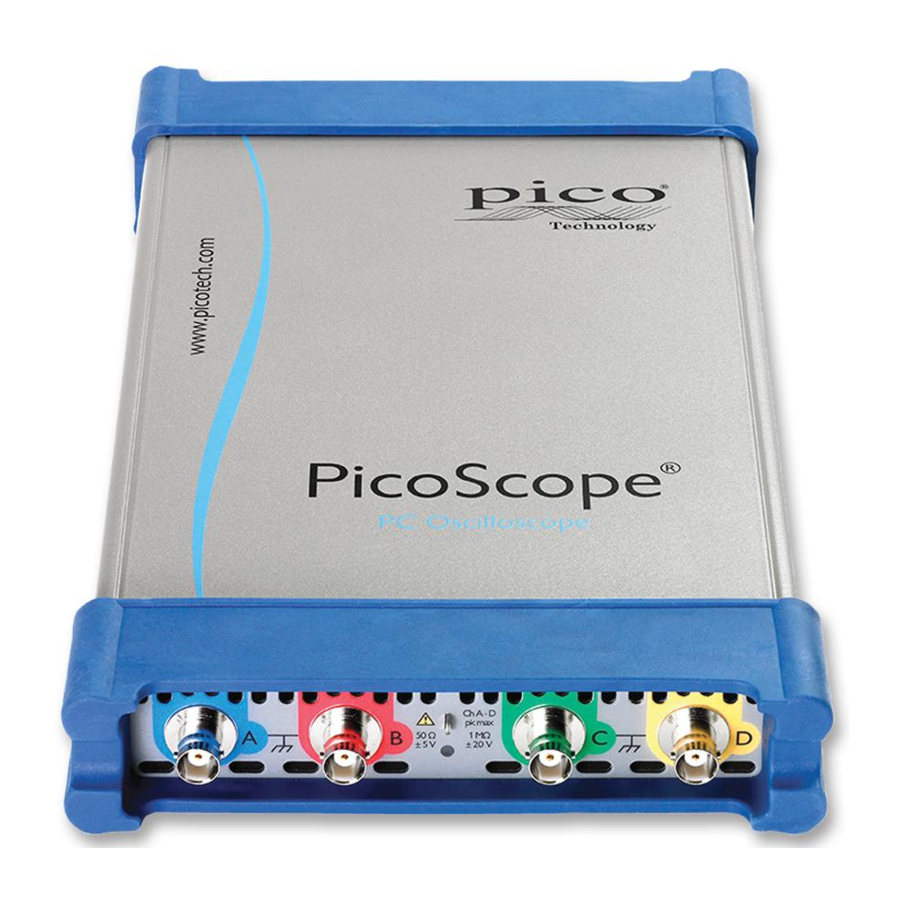
Page 11: Connections
Connections Standard oscilloscope connectors The PicoScope 6000 Series oscilloscopes have standard BNC input and output connectors. The channel inputs have switchable impedances of 50 Ω or 1 MΩ. In high-impedance mode, they are compatible with all standard scope probes including 10:1 attenuated types. - Page 12 K. Air vents (present on the front and back of the scope). CAUTION To prevent overheating and other damage, do not block the air vents or insert any objects through them. ps6000abcd.en r3 Copyright © 2012-2016 Pico Technology Ltd. All rights reserved.
-
Page 13: Glossary
USB 3.0. A USB 3.0 port uses signaling speeds of up to 5 gigabits per second and is backwards-compatible with USB 2.0 and USB 1.1. Vertical resolution. A value, in bits, indicating the number of voltage levels that the oscilloscope can distinguish. Copyright © 2012-2016 Pico Technology Ltd. All rights reserved. ps6000abcd.en r3... - Page 14 –100 mV and +100 mV. Input voltages outside this range will not damage the instrument as long as they remain within the protection limits stated in Safety warnings. ps6000abcd.en r3 Copyright © 2012-2016 Pico Technology Ltd. All rights reserved.
-
Page 15: Index
External trigger Scope probe Signal generator output Software license conditions FCC notice Trademarks Grounding Trigger external Installation Upgrades cable changing ports Low Voltage Directive (LVD) Warranty Mains voltages Copyright © 2012-2016 Pico Technology Ltd. All rights reserved. ps6000abcd.en r3...
Need help?
Do you have a question about the PicoScope 6000 Series and is the answer not in the manual?
Questions and answers