Table of Contents
Advertisement
Quick Links
Advertisement
Table of Contents

Related Manuals for TILMOR 520M


Summary of Contents for TILMOR 520M
- Page 1 Operators Manual Tractor 520M Gasoline Original Operator’s Manual 12-10005 Rev.02...
-
Page 2: Table Of Contents
TABLE OF CONTENTS INTRODUCTION PAGE 6 Product Description ..........................6 Intended Use ............................6 Replacement Parts ..........................6 Using Your Manual ..........................7 Manual Glossary ............................7 SAFETY PAGE 8 Safety Decals ............................8 Training Required ..........................11 Personal Protective Equipment Requirements ..................11 Operation Safety ..........................11 Preventing Accidents ..........................12 Keep Riders Off ............................12 Mounting and Dismounting the Tractor ....................13... - Page 3 TABLE OF CONTENTS Hazard Flasher Switch (AA) .........................25 Head Light Switch (BB) ........................25 Implement Light Switch (CC) .......................25 12 Volt Front Switch (DD) and 4 Pin Socket (OO) ................25 Front Work Light Switch (EE) .......................25 Rear Work Light Switch (FF) ........................25 Directional Signal Switch (HH) ......................25 Horn Switch (II) ............................26 Rear Auxiliary Quick Couplers (LL) ......................26...
- Page 4 Long Term Storage (4 Months or Longer) ....................46 Short Term Storage (Less than 4 Months) ...................46 Removing the Power Unit from Storage ....................46 Maintenance Schedule .........................47 Maintenance Checklist .........................48 Tilmor Maintenance Log ........................49 Tilmor Maintenance Log ........................50 Engine ..............................51 Engine (Continued) ..........................52 Hydraulic ..............................52 Electrical ..............................53...
- Page 5 Load Capacities ...........................60 Fluid Capacities & Specifications ......................60 WARRANTY PAGE 61 Return Policy & Procedure ........................61 Warranty ...............................61 Non-serialized Product - 1 Year ......................61 Serialized Product - 2 Year or 1000 hours ...................61 Tilmor Warranty Policy .........................61 Tilmor Warranty Procedure ........................61...
-
Page 6: Introduction
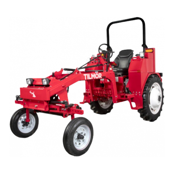
Tilmor products, and resources. Product Description The Tilmor 520M tractor is the ultimate row crop tractor for diversified farming operations. The Tilmor 520M is highly adaptable to meet the needs of a multitude of crops and cultural practices. Intended Use This tractor is designed solely for use in customary agricultural or similar operations. -
Page 7: Using Your Manual
A piece of Tilmor equipment that requires a Tilmor tractor for operation. Accessory A device that attaches to a Tilmor tractor or Attachment to extend its capabilities. Machine Describes any “Implement” or “Accessory” that is used in conjunction with a Tilmor tractor. -
Page 8: Safety
Keep all safety decals legible. Remove all grease, dirt, and debris from safety decals and instructional labels. If any decals are faded, illegible, or missing, visit www.tilmor.com or call 1-844-255-5864 for replace- ments. When replacement or new components are installed, be sure that current safety decals are affixed to the replacement or new part. - Page 9 SAFETY 1. Wear eye protection, such as gog- gles or a face shield, when checking or servicing batteries. 2. Wear appropriate protective gear, 1. Read the manual before operating the tractor. such as rubber gloves and an 2. Wear personal protective equipment, such as safety apron, when checking or servicing glasses, closed toe shoes or boots, and ear protection.
- Page 10 SAFETY 1. DANGER: Explosion/Fire Hazard 2. Keep away from fire, sparks, and pilot lights when refueling or storing tractor and fuel. 3. Smoking is prohibited. Decal Description Part Number Quantity Operator Safety 00-0548 Warning - Pinch Point 00-0218 Warning - Battery 00-0366 Warning - Hot Surface 00-0374...
-
Page 11: Training Required
SAFETY General Safety Procedures for Tilmor Tractors, Implements, & Accessories Training Required • The owner of this machine is solely responsible for properly training the operators. • The owner/operator is solely responsible for the operation of this machine and prevention of accidents or injuries occurring to him/herself, other people or property. -
Page 12: Preventing Accidents
SAFETY General Safety Procedures for Tilmor Tractors, Implements, & Accessories Operation Safety (continued) • Stop operation immediately at any sign of equipment failure. An unusual noise can be a warning of equip- ment failure or a sign that maintenance is required. Make all necessary repairs before operating the machine again. -
Page 13: Mounting And Dismounting The Tractor
SAFETY General Safety Procedures for Tilmor Tractors, Implements, & Accessories Mounting and Dismounting the Tractor • To prevent falling accidents always face the machine when mounting or dismounting. Maintain three points of contact with steps and hand holds. • Never mount or dismount a moving machine. -
Page 14: Towing Loads
Keep all safety decals legible. Remove all grease dirt, and debris from safety decals and instructional labels. • If any decals are faded, illegible, or missing, replacements can be obtained at www.tilmor.com. • When new components are installed, be sure that current safety decals are affixed to the replacement com- ponents. -
Page 15: Fuel Safety
SAFETY General Safety Procedures for Tilmor Tractors, Implements, & Accessories Fuel Safety • To avoid personal injury or property damage, use extreme care in handling gasoline. Gasoline is extremely flammable and the vapors are explosive. • Do not refuel the machine while smoking or at a location near flames or sparks. -
Page 16: Roll Over Protective Structure (Rops)
SAFETY 520M Tractor Safety Procedures Roll Over Protective Structure (ROPS) WARNING WARNING Keep the ROPS locked in the upright position and Alterations or modifications to this machine and/ the seat belt securely fastened during operation. or the ROPS structure can reduce safety and could Failure to do so could result in serious injury or loss cause damage to the machine. -
Page 17: Operator Safety Interlock System
SAFETY 520M Tractor Safety Procedures Operator Safety Interlock System The Tilmor 520M Tractor is equipped with a safety interlock system. This system: • Prevents the engine from starting unless the operator is present in the seat. • Prevents the engine from starting unless the transmission is in neutral. -
Page 18: Testing The Safety Interlock System (Continued)
SAFETY 520M Tractor Safety Procedures Testing the Safety Interlock System (continued) Tests 1-4 test the ‘Engine Start’ function. For each test, ensure that the parking brake is engaged and the high/low range shift lever is in the neutral position. As listed below for each test put the transmission in gear or neutral position, ensure there is or is not an operator present in the seat, and engage or disen- gage the BPTO if equipped. -
Page 19: Operational Controls
OPERATIONAL CONTROLS OPERATIONAL CONTROLS Standard Operational Control Locations Use the following images to help identify the loca- tions of operational controls. The letter next to each control can be referenced to the list that follows these images. A. Speedometer B. Tachometer C. -
Page 20: Optional Operational Control Locations
OPERATIONAL CONTROLS OPERATIONAL CONTROLS Optional Operational Control Locations Use the following images to help identify the loca- tions of operational controls. The letter next to each control can be referenced to the list that follows these images. Rear Hitch Arms Rear Hitch Arms Front Hitch Arms Front Hitch Arms... -
Page 21: Optional Operational Control Locations
OPERATIONAL CONTROLS Optional Operational Control Locations RR. Seat Slide Lever SS. Lumbar Support Knob Use the following images to help identify the loca- TT. Seat Back Angle Adjustment Lever tions of operational controls. The letter next to each control can be referenced to the list that follows UU. -
Page 22: Speedometer Cluster Gauge (A)
OPERATIONAL CONTROLS OPERATIONAL CONTROLS Speedometer Cluster Gauge (A) Tachometer Gauge Cluster (B) The speedometer gauge contains a speedometer, The tachometer gauge contains a water high tem- BPTO indicator light, glow plug indicator light, and perature indicator light, tachometer, low voltage parking brake indicator light. -
Page 23: Ignition Switch (C)
OPERATIONAL CONTROLS Ignition Switch (C) 4 Speed Transmission Gear Shift Lever (F) Provides four forward travel speeds and one reverse speed. Using the 4 speed gear shift lever and the 2 speed high/low range shift lever in different combinations provides eight forward speeds and two reverse speeds. -
Page 24: Choke (J)
1. Highest Position The brake pedals are used together to stop the 2. Lowest Position tractor. The Tilmor tractor is equipped with indepen- The depth control dent brake pedals for the left and right rear wheels. handle allows the... -
Page 25: Hazard Flasher Switch (Aa)
OPERATIONAL CONTROLS Hazard Flasher Switch (AA) Front Work Light Switch (EE) 1. On 1. On 2. Off 2. Off Depressing the top portion of Depressing the top portion of the front the hazard switch flashes both work light switch turns on the front directional turn signal lights. -
Page 26: Horn Switch (Ii)
1. Aux Hydraulic Couplers Direction #1 implements mounted 2. Aux Hydraulic Couplers Hold on the mid mount 3. Aux Hydraulic Couplers Direction #2 of the Tilmor tractor. Moving the front hydraulic control Lift the BPTO handle lever forward or backward controls upwards to engage the auxiliary functions of mid mounted the BPTO. -
Page 27: Hoist Retaining Pin (Xx)
OPERATIONAL CONTROLS Hoist Retaining Pin (XX) The retaining pin secures the implement hoist in place on the tractor. The retaining pin should be installed at all times. Winch Handle (YY) The winch handle is used to operate the hoist. Cranking the handle clockwise retracts the cable (lifts the implement). -
Page 28: General Operation
Use of starting fluids could result in engine dam- age and/or personal injury. The Tilmor 520 tractor is equipped with an interlock system for operator safety. The safety interlock system requires the tractor transmission to be in the neutral position, and an operator to be seated on the tractor. -
Page 29: Driving The Tractor
GENERAL OPERATION Driving The Tractor Emergency Stopping The Tractor 1. Depress the clutch CAUTION 2. Depress both brake pedals evenly. 3. Turn the ignition key to the off position. The tractor must be at a complete stop before 4. Set the parking brake. shifting the two speed transmission. -
Page 30: Implement Hoist
5. Close the hitch arm latches ensuring the imple- ment or tool bar is securely locked in place. The track width of the Tilmor 520 series tractor is Implement Hoist adjustable from 50” on center to 78” on center in 2”... - Page 31 5. Remove the wheel from the tractor. 12. Adjust the other side of the front axle in the same 6. Reference the chart below to reach the desired manner as required. track width for your Tilmor tractor. Wheel Offset Track Width Rim Orientation* Dish Orienta-...
-
Page 32: Ballast
Towing • Ensure that enough ballast is used on the front The Tilmor 520 series tractor is capable of towing of the tractor to ensure sufficient weight for loads up to 2000 lbs (907 kg). The receiver style steering. -
Page 33: Service
If any component of the 520 series tractor requires replacement, use only original Tilmor replacement parts. Tilmor replacement parts are available on our website at www.tilmor.com or reach a customer service representative at 1-844-255-5864. Cleaning And Appearance Care For best results, and to maintain the finish of the power unit, clean or wash the power unit to remove accumulated dirt and debris when the job is finished. - Page 34 SERVICE 4. Seat (D). 7. Brake Master Cylinder Access Panel (G). Fuse Block Access Cover (E). Fuel Shut Off Valve Access Cover (F). Service - 34...
-
Page 35: Lubrication Locations
SERVICE Lubrication Locations 5. Front Hitch Cylinder Lubrication is required at the following locations. Refer to the maintenance schedule for service inter- vals and amount of grease. Refer to the Specification section for grease type. 1. Outer Tie Rods 6. Rear Hitch Cylinder 7. -
Page 36: Checking Hydraulic Fluid Level
SERVICE Checking Hydraulic Fluid Level Checking Engine Oil Level Check the hydraulic fluid level when the hydraulic Attention system is cold, prior to operating the tractor. If the hydraulic system is warm, allow one hour for the Avoid Engine Damage! hydraulic system to cool before checking the fluid Failure to check the oil level regularly could lead level. -
Page 37: Changing Air Filter Elements
SERVICE Changing Air Filter Elements 7. Insert the dipstick back into the engine and remove again. CAUTION 8. Check the oil level. The level should be between the Full (C) and Add (D) marks on the dipstick. When the air filter elements are removed, an opening is created to the internal parts of the engine. -
Page 38: Filling The Fuel Tank
SERVICE Filling The Fuel Tank 6. Release both latches (C) on the filter assembly and unhook the latches from the filter housing. DANGER Fuel is flammable and/or explosive. Follow all safety instructions in the Fuel Safety section of this manual and in the engine operators manual. WARNING Long term exposure to fuel vapors can cause serious injury or illness. -
Page 39: Checking The Brake Fluid
SERVICE Checking the Brake Fluid Checking the Transmission Fluid 1. Park the tractor on a level surface. 1. Park the tractor on a level surface. 2. Engage the parking brake and shut off the 2. Engage the parking brake and shut off the engine. -
Page 40: Checking Drive Belts
SERVICE Checking Drive Belts Adjusting The Drive Belts Tension WARNING WARNING Avoid Personal Injury! Avoid Personal Injury! Fingers or loose clothing can get caught in Fingers or loose clothing can get caught in rotating rotating parts. Shut off the power unit engine, parts. -
Page 41: Adjusting Hydraulic Pump Belt Tension
SERVICE 9. Checking The Hydraulic Pump Belt Adjusting Hydraulic Pump Belt Tension WARNING WARNING Avoid Personal Injury! Avoid Personal Injury! Fingers or loose clothing can get caught in Fingers or loose clothing can get caught in rotating rotating parts. Shut off the power unit engine, parts. -
Page 42: Cleaning Engine Compartment & Engine
SERVICE Cleaning The Battery and Terminals 7. Loosen the 3/8” flange nut (B). 1. Park the tractor on a level surface. 2. Engage the parking brake and shut off the engine. 3. Remove the key from the ignition switch. 4. Tilt the seat forward and fasten in place with the seat prop. -
Page 43: Jump Starting Procedure
LEDs and do not use (negative booster cable first). a replaceable bulb. If a light is no longer function- ing the entire light must be replaced. Replacement lights can be purchased at www.Tilmor.com Service - 43... -
Page 44: Bpto Belt Inspection
SERVICE BPTO Belt Inspection 4. Lean the operators seat forward. 5. Remove the inspection cover (A) from the trans- WARNING mission. Always set the parking brake, shut off power unit engine, remove the ignition key, and ensure all moving parts have come to a complete stop before inspecting components or attempting any repair or adjustment. -
Page 45: Steering Wheel Adjustment
SERVICE Tire Pressure 8. Adjust the stop bolt in or out until the desired distance is achieved. Check the tire pressure prior to operation, as part 9. Adjust the brake pedal adjustment rod (E) so of the daily inspection. Keep tire inflation within the that the brake pedal is 1/4”... -
Page 46: Parking Brake Inspection & Adjustment
SERVICE Parking Brake Inspection & Adjustment 15. Grease and lubricate all points specified in the maintenance section. Wipe off any excess 1. Park the tractor on a level surface. grease or oil. 2. Shut off the engine and remove the key from the After the above steps have been performed, com- ignition switch. -
Page 47: Maintenance Schedule
Torque to 130 ft-lbs (176 Nm) * If heavy load, high temperature, or dusty condition service intervals are not specified, Tilmor recommends servicing more frequently at 1/2 the standard service interval. ** Operation in severe conditions may require more frequent service intervals. -
Page 48: Maintenance Checklist
Torque to 130 ft-lbs (176 Nm) * If heavy load, high temperature, or dusty condition service intervals are not specified, Tilmor recommends servicing more frequently at 1/2 the standard service interval. ** Operation in severe conditions may require more frequent service intervals. -
Page 49: Tilmor Maintenance Log
SERVICE Tilmor Maintenance Log Model Number: ______________________ Serial Number: __________________________ Date: Hours: Description of Repairs/Service Initials Service - 49... -
Page 50: Tilmor Maintenance Log
SERVICE Tilmor Maintenance Log Date: Hours: Description of Repairs/Service Initials Service - 50... -
Page 51: Engine
TROUBLESHOOTING Engine Symptom: Possible Cause: Starter will not engage. Battery disconnect switch is in the Off position. Blown fuse. Tractor transmission is not in neutral. Low battery voltage. BPTO is engaged (if equipped). Engine cranks, but will not start. Fuel shut-off valve is turned off. Insufficient fuel level. -
Page 52: Engine (Continued)
TROUBLESHOOTING Engine (Continued) Symptom: Possible Cause: Oil light comes on when running. Low oil level. Faulty oil sender. Faulty or plugged oil pump. Excessive fuel consumption. Plugged or restricted air filters or hose. Dirty or faulty fuel injectors. Excessive oil consumption. Check for leaks. -
Page 53: Electrical
TROUBLESHOOTING Electrical Symptom: Possible Cause: Battery does not charge. Loose or corroded connections. Broken or loose wire in the charging system. Blown fuse in the charging system. Defective battery. Loose alternator belt. Defective alternator. Lights are inoperable. Blown fuse. Broken wire. Defective Light Switch. -
Page 54: Wiring Circuit - Main Power / Ignition Switch Schematic
TROUBLESHOOTING Wiring Circuit - Main Power / Ignition Switch Schematic A-147-BLK-12 A-133-RED-12 A-126-RED-18 A-148-RED-18 A-127-RED-18 Troubleshooting - 54... -
Page 55: Wiring Circuit - Gauges / Usb / Aux / Misc Fuse Block Schematic
TROUBLESHOOTING Wiring Circuit - Gauges / USB / AUX / Misc Fuse Block Schematic A-073-RED-18 A-072-RED-18 A-071-RED-18 Troubleshooting - 55... -
Page 56: Wiring Circuit - Operation Interlock Schematic
TROUBLESHOOTING Wiring Circuit - Operation Interlock Schematic A-014-BLK-18-GXL A-141-RED-18 A-090-BLK-18 A-089-BLK-18 A- 0 8 0-BRN-18 A-080-BRN-18 A-002-BRN-18 A-226-GRN-18 D-131-BLK-18 D-103-BRN-18 D-002-BRN-18 D-226-GRN-18 Troubleshooting - 56... -
Page 57: Wiring Circuit - Engine Functions / Diesel - Gas Schematic
TROUBLESHOOTING Wiring Circuit - Engine Functions / Diesel - Gas Schematic A-137-RED-18 A-102-BLU-12 A-100-BLU-12 Troubleshooting - 57... -
Page 58: Wiring Circuit - Head & Tail Light - Directional / Hazards Schematic
TROUBLESHOOTING Wiring Circuit - Head & Tail Light - Directional / Hazards Schematic A-066-RED-18 A-063-RED-18 A-064-RED-18 A-065-RED-18 A-150-BLK-18 A-165-YEL-18 A-166-YEL-18 Troubleshooting - 58... -
Page 59: Specifications
Attachment System ........Tilmor... - Page 60 Weight** ........2750 lbs (1247 kg) Tilmor LLC. Reserves the right to change any specifications without notice.
- Page 61 (whichever comes first). Warranties on serialized Tilmor products are transferable. Tilmor Warranty Policy Tilmor LLC may opt to repair, replace, or issue a refund for Tilmor products that are defective or have sus- tained damage in shipping. The following actions and damages are excluded from warranty: •...
Need help?
Do you have a question about the 520M and is the answer not in the manual?
Questions and answers