
Related Manuals for FARMTECH FDD 3000

Summary of Contents for FARMTECH FDD 3000
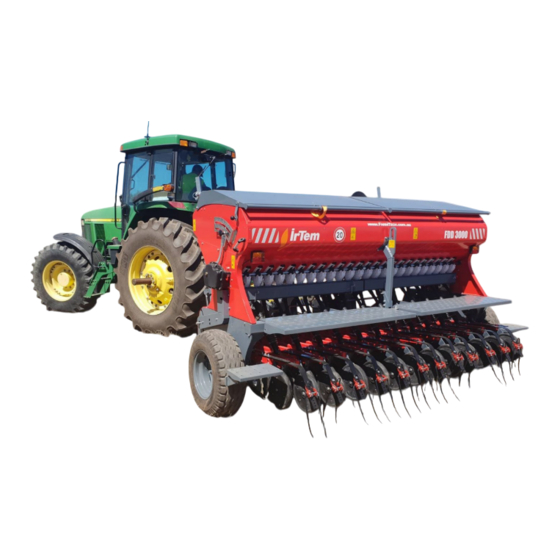
- Page 2 Dear Customer, Thank you for choosing the FarmTech/ Irtem brand. FarmTech have been working with Irtem for over a decade to adapt some of their seed drills to suit the Australian conditions. FarmTech look forward to working with our customers with any future product development or improvements.
-
Page 3: General Information
A. General Information A.2. User Information A.1.1. Delivery Form First and Last Name: Address Telephone Machine Model Delivery Date Authorized Deliverer : Has the final inspection of the product been carried out? Have the initial settings been made? Has the initial use training been provided? Service Signature Customer Signature... - Page 4 A.2.3. Safety Rules for Agricultural Equipment Use A.3. Qualifications and Technical Specifications A.3.1. Qualifications of Your Grain Drill A.3.2. FDD 2500 Technical Specifications A.3.3. FDD 3000 Technical Specifications A.4. Machine Sections A.4.1. Box Part A.4.1.1. Screens A.4.1.2. Automatic Box Covers A.4.1.3.
- Page 5 B. Connection with Tractor B.1. Mechanical Connection B.2. Hydraulic Connections B.3. Electrical Connections B.4. Tracking System (Work Computer) Connection C. Adjustments C.1. Seed and Fertilizer (Spread Amount) Spread Norm Adjustment C.1.1. Switching the Funnel Trays to Test Position C.1.2. Hopper Adjustments C.1.2.1.
- Page 6 C.9. Seed/Fertilizer Level Gauges and Resetting C.10. Tracking and Work Computer Use C.10.1. Operating C.10.2. Settings C.10.2.1. Number of Signals Generated in a Round C.10.2.2. Wheel Diameter C.10.2.3. Number of Tracking Rounds C.10.2.4. Seed Shaft Control C.10.2.5. Working Width C.10.3 Shortcut Tracking Settings Buttons C.10.4 Manual Tracking Control C.10.5 Resetting Working Field Data D.
- Page 7 A.2. Safety Warnings A.2.1. Warning Signs READ THE USER MANUAL Read the user manual carefully before using. STOP THE ENGINE AND REMOVE THE IGNITION KEY Stop the tractor and remove the ignition key before the maintenance/repair. CRASHING HAZARD Do not stand behind the tractor.
- Page 8 FALLING HAZARD Do not climb on the machine during operation. HAND JAMMING HAZARD Do not insert your hand into the moving parts during operation. MARKER CRASH HAZARD Do not stand on the lowering, lifting and forward route of the markers. Do not approach the moving machine.
- Page 9 SUSPENSION POINT Only connect the marked points during the machine loading. ROTATING DEVICES There are rotating mechanisms that may cause accidents and injuries on the machine in case failing to follow the instructions. CRASHING HAZARD Do not approach the tractor and equipment during operation.
- Page 10 A.2.1.1 Introduction 37 of each 100 fatal accidents occur in agriculture industry. Compared to other business lines, this ratio makes farming the most dangerous business line today. The significant part of the accidents experienced in the agriculture industry is caused as a result of users failing to obey the “safety rules and instructions”.
- Page 11 7. Tractor must never be used unintendedly. 8. Tractor must be serviced and maintained in a timely and complete manner in accordance with the instructions given in the instructions of use and manual come with the tractor. 9. Loose clothes must not be worn when working with tractor. Loose clothes may be captured by the moving parts of tractor such as exposed joint, belt and pulley during operation and cause serious accidents resulting with injury or death.
- Page 12 18. Be careful and slow down when towing heavy load and only use a tow hook in towing. Towing must be carried out by using central suspension and side drawbar if an appropriate coupling arrangement does not exist. Failure to do so may impair the center of gravity of tractor and lead to rearing/front lifting.
- Page 13 32. When driving down a steep slope, the engine brake at an appropriate gear must be used and the slope must never be climbed down by using the clutch and/or by shifting the gear to neutral. 33. The traffic signs and rules must be observed when driving in the highway traffic. 34.
- Page 14 47. When tractor is moving, do not climb over the drawbar assembly or towed agricultural tool and machine, do not stand among the tractor and machine and do not attempt to make any adjustment on the tractor and/or coupled equipment. 48.
- Page 15 6. Never stand among the tractor and machine when adjusting the levers of the 3-point suspension system. The system controlling the hydraulic suspension levers must be necessarily locked when travelling on the road open to traffic and the machine is suspended.
- Page 16 Extra weights attached to machine and tractor adversely affect the maneuver and braking capability of tractor. Use tractor more carefully and slowly since this situation will reduce the driving safety. 19. Be careful when turning. The weight, width and centrifugal force of the equipment engaged to tractor may take tractor out of control.
- Page 17 A.3. Qualifications and Technical Specifications A.3.1. Qualifications of Your Grain Drill Before using your grain drill, getting to know the qualifications, intended purposes, capabilities and superior aspects of the product you purchased is essential to obtain maximum benefit from your machine. Thus, your grain drill is designed to make seeding;...
-
Page 18: Specification
A.3.2 FDD 2500 Technical Specifications Specification With Without fertilizer fertilizer Box capacity (total liters) 1500 L 1520 L Seed Box 910 L 1520 L Fertilizer Box 590 L Working Width 250 cm 250 cm Row Spacing 12.5 cm 12.5 cm No of Coulters 20 double disc 20 double disc... - Page 19 A.3.3 FDD 3000 Technical Specifications Specification With Without fertilizer fertilizer Box capacity (total liters) 1780 L 1800 L Seed Box 1080 L 1800 L Fertilizer Box 700 L Working Width 300 cm 300 cm Row Spacing 12.5 cm 12.5 cm...
- Page 20 A.4. Machine Sections Your grain drills consists of following main sections each having different tasks: 1. Box Part 2. Frame Part 3. Tow Part 4. Coulter Frame Part 5. Clutch Mechanism 7. Coulter 8. Calibration Mechanism It also has auxiliary equipment that can be added on machine optionally;...
- Page 21 When extra screen need arises for the seed box, 12 screens will be required and they are available optionally. Box with screens in both seed and fertilizer sections (on the left) FDD 2500 - FDD 3000 Screen Distribution Table With fertilizer Without fertilizer Fertilizer Partition 8 (standard)
- Page 22 Handle Lock Bolt Tension Adjustment Slots Lock Release Handle Gas Piston Inserts A.4.1.3. Separators Separators preventing seed residues to remain in the seed box, hopper areas and bottom area of your drill as well as preventing the accumulation of the seeds in the center due to vibration are equipped.
- Page 23 A.4.1.4. Hoppers It is the section ensuring the distribution of the seeds and fertilizer inside the machine on the field to be cultivated at desired amount (spread norm) and row spacing. It provides controlled discharge of the seed and fertilizer entering through free flow according to the running speed of the machine.
- Page 24 A.4.1.5. Variable-Speed Transmission Variable-speed transmission is a closed system transmission mechanism capable of varying the motion from the wheel to rotate the seed and fertilizer gears at a required ratio and in a “stepless” manner. Variable-speed transmission and components (on the left) 1.
- Page 25 A.4.2. Frame Part Your grain drill has a uniform frame made of ST52 quality steel and designed for use in harsh conditions. All the components on the frame has rigid form; the sections such as box part, draw bar part, marker mechanism, calibration mechanisms, platforms and coulters are positioned on this frame.
- Page 26 A.4.3. Drawbar Part 1. Tow Bar 2. Warp 3. Warp Height Adjustment Block 4. Hose Guide Draw bar and main parts Drawbar part equipment Drawbar part connection tractor connection Drawbar part is the part providing the connection of the grain drill with the tractor. At the same time, this part which also providing the adjustment of the parallelism of the machine to the ground can be folded by bringing it to vertical position when the equipment...
- Page 27 A.4.4. Coulter Frame Part Coulter frame is the part connecting the coulters to the main frame. The coulter frame functioning with off-center parallelogram system is coupled to the main frame with two bottom swings and two slope adjustment jacks. The coulter frame can change the front and rear slope by the extension and contraction of the slope adjusting jacks that are connected to the upper section.
- Page 28 A.4.4.1. Slope Adjusting Jacks It is the part connecting the coulter frame part to the main frame. They are coupled to the top point of the coulter frame and both jacks can be adjusted simultaneously with a single movement thanks to the tubular shaft placed between them.
- Page 29 A.4.5. Clutch Mechanisms Seed Fertilizer Clutch Clutch A.4.5.1. Clutch The models with fertilizer (seed clutch and fertilizer clutch) have 2 and the models without fertilizer (only seed clutch) have 1 clutch mechanism. (on the top) The primary duty of the clutch mechanisms is to stop the seed and fertilizer flow when the coulters are disengaged from the soil.
- Page 30 A.4.5.2. Bottom and Top Clutch Actuators 1. Top Clutch Actuator 2. Bottom Clutch Actuator The components connecting the clutch mechanism with the coulter frame are top and bottom actuators. Actuators are driven by the coulter frame. With this triggering, the clutch mechanism enables the motion from the wheel to be transferred to the variable-speed transmission or stopping the progressing motion.
- Page 31 A.4.6. Platform and Steps 1. Loading Platforms 2. Steps A.4.6.1. Loading Platforms Your grain drill is equipped with a 2-piece loading platform that allows the person working to move comfortably during seed and fertilizer loading. The height of the loading platform from the ground is 88 cm. The platform height was determined to consider the average base height of the agricultural trailers with capacity of 4 –...
- Page 32 A.4.6.2. Tire Scraper Steps Your grain drill is equipped with 2 steps that allow climbing on the loading platform on both sides and serving as mud scraper for the right and left tire. The position of the steps is designed in adjustable structure in order to prevent performance loss of the scrapers in case tire wear.
- Page 33 A.4.7.1. Harrow Mechanism The harrow mechanism used in your grain drill has a breaking protection and adjustable pressure, height and slope setting. Also, it can be disabled when not required. For the adjustments of harrow mechanism refer to: (C.10. Harrow Adjustments) 1.
- Page 34 A.4.8. Calibration Mechanism The calibration mechanism is positioned between the hoppers and the seed pipes connected to the coulters and hence they are used to determine the seed to be delivered to the coulters during calibration. In this way, it allows the seeding norm (amount of seed and fertilizer to be spread) that will be applied to be properly and easily measured during seeding.
-
Page 35: Optional Parts
A.4.9. Optional Parts A.4.9.1. Hydraulic Marker System It is the marker system part which, during operation, guides the operator by marking the next passing route of the tractor and also provides a homogenous seed/fertilizer distribution on the field surface. Negativities such as overlapping rows and repetitive seeding or remaining gaps between passages are avoided thanks to the marker system. - Page 36 A.4.9.2 Tracking System and Work Computer (NOT AVALIABLE IN AUSTRALIA) Work computer is a software controlled electronic unit transmitting the; Instant moving speed (km/h) and Total work done information needed during seeding to operator. Work computer also has the functionality of controlling the automatic tracking operation.
- Page 37 B. Connection with Tractor B.1. Mechanical Connection Follow the procedure steps to connect tractor and equipment: 1. Step: Switch the drawbar from parking position to working position (Refer to A.4.3. Drawbar). The drawbar switched to working position must be parallel to the ground.
- Page 38 1. Connecting Pin 2. Safety Catch 3. Warp height adjustment block slots 4. Warp height adjustment connecting pins...
- Page 39 B.2. Hydraulic and Electrical Connections Your grain drill has 3 hydraulic lifts in total (1 piece) on the depth adjusting mechanism and (2 pieces) on the hydraulic marker system and these lifts must be connected with tractor before operation. Minimum 3 drive assemblies (6 hydraulic outlets) are required on the tractor for the hydraulic systems on your grain drill to function properly.
- Page 40 The structures of the jacks are designed to be different to prevent the confusion of the marker jacks and the depth adjustment lift jacks when connecting the hydraulic jacks and the tractor. The hydraulic jacks of the depth adjustment lift of standard construction with no additional equipment.
- Page 41 B.4. Tracking System Connection The equipment and sensor necessary to use of the system in the models with tracking system come as assembled on your grain drill. The installation procedure steps you need to follow to use the system over tractor are described below: 1.
- Page 42 C. Adjustments C.1. Seed and Fertilizer (Spread Amount) Spread Norm Adjustment The determination of the amount of seed and fertilizer that you desire to use for unit area during seeding is referred as spread norm adjustment. Your grain drill is intended to spread the desired amount of seed and fertilizer between 2kg and 400 kg per hectare with high precision.
- Page 43 Follow the procedure steps below to switch the funnel trays to test position. 1. Step: Remove the R pins retaining the test container in its slot (2 in each test container) and then remove the test container and put it in a safe place. 2.
- Page 44 C.1.2. Hopper Adjustments Hopper adjustments are determined according to the physical structure, size and row spacing requirement of Slide Cover the seed to be planted. Seed Gear (sheave) Hopper and throttle adjustments positively or negatively Sight Glass affect the seeding norm (amount of seed to be spread). Gear Shaft However, the primary objective of the hopper adjustments is not setting the spread norm but maintaining the spread...
- Page 45 Note - 1: Seed and fertilizer flow to the desired hoppers can be disabled by switching the slide cover to closed position. Slide covers are adjusted as follows; a row spacing of 25 cm when in 1 open and 1 closed state, a row spacing of 37.5 cm in 1 open 2 closed state, 1 a row spacing of 50 cm in 3 open state.
- Page 46 C.1.2.2 Throttle, Throttle Adjustment and Throttle Resetting C.1.2.2.a. Throttles Throttles are inclined components in suitable shape transmitting the seed and fertilizer entering the box to the sheave (gear). Its duty is to enable gears to flow regularly and uniformly and to protect the limited seed against being damaged by the gear.
- Page 47 C.1.2.2.b. Throttle Adjustment Throttles are adjusted in following procedure steps: Note: It is recommended to fill the box with seed and/or fertilizer to be used by 50% before the adjustment. Throttle Adjustment Scale Throttle Adjustment Throttle Adjustment arm and Throttle Adjustment Scale 1.
- Page 48 and 4 steps are repeated until a proper flow is achieved. The adjustment is completed once the desired seed flow is achieved. Correct adjustment: is that “fertilizers pass Important: between the throttle and gear freely without being crushed” but “the seed/fertilizer flow stops completely” when the machine rises from the ground, i.e.
- Page 49 4. Step: Resetting is completed when all the throttles are aligned. Note: Although the slide cover throttle and gear adjustments described above affect the spread amount, it should not be used for this purpose. The primary objective of the hopper adjustments is to enable a regular and stable fertilizer flow and to prevent the potential deviations in the spread amount.
- Page 50 The working positions of the gears according to the seed type and amount are listed below: The “narrow gear” in the middle operates 1. Position: as single. It is used to plant the seeds having a size of 0.5 – 2.5 mm and a spread amount per unit area (seeding norm) of 2 –...
- Page 51 You will find the seed amount to be spread per 1 hectare when you multiply the result with the coefficient of the model of your grain drill. Grain Drill Model Crank Handle Turn Count Coefficient FDD 2500 FDD 3000 Coefficient Table...
- Page 52 Adjustment Example: Let us plan wheat plantation with our FDD 3000 grain drill having a working width of 3 meters: Slide Covers: to 2. position Throttles: to B position Gears: to 3. Position In the Step 8 (when we rotate the crank handle by 20 complete turns), we scale the seeds dropped into the test container.
- Page 53 8. Step: The amount of the seed to be spread is adjusted by changing the position of the “transmission adjusting arm” on the variable-speed transmission. Loosen the fixing knob on the arm before the procedure. Spread amount decreases if scale the value on the scale decreases.
- Page 54 C.2. Depth Adjustment Mechanism and Travelling/Working Positions of Coulters Seeding depth adjustment and switching the coulters to travelling position are realized with the depth adjustment mechanism deployed at the center of the grain drill. Locking Shaft Limiting Limiting Flange Flange Depth Adjustment Depth...
- Page 55 C.2.2 Travelling and Working Positions of Coulters The coulters are switched to travelling position by following the procedure steps below. 1. Step: Lift the coulters completely by using the tractor hydraulic control. 2. Step: Remove the locking shaft retaining the depth adjustment rings.
- Page 56 C.2.3 Depth Adjustment Rings Seeding depth is adjusted by the limitation of the piston stroke by the depth limiting rings on the depth adjustment mechanism. The depth adjustment mechanism has 12 depth adjustment rings moving independently from each other. These rings are adjusted by opening from top to bottom subsequently or closing from bottom to top subsequently.
- Page 57 Correct Depth Adjustment (for a seeding depth of approx. 3.5 – 4 cm) CAUTION: Jamming Hazard Do not hold your hand and/or any limb on the limiting flange and/or depth adjustment rings during depth adjustment and changing the travelling/working positions. Stop the tractor and lock the hydraulic system during adjustment.
- Page 58 C.2.4 Seeding Depth Adjustment Follow the procedure steps below for seeding depth adjustment: 1. Step: Remove the locking shaft. 2. Step: Open the plastic chock and 10 depth adjustment rings on the top. 3. Step: Lower the coulters on the ground when moving on the field to be cultivated.
- Page 59 Once you lift and lower the coulters, they will not be lower below the limit that you determined with the depth adjustment rings and maintain the seeding depth in any circumstances. 7. Step: Attach the locking shaft. Note: If the locking shaft is not attached, the depth adjustment rings may be partially or completely closed and undesired circumstances may occur due to the vibration to be generated during operation.
- Page 60 C.3. Slope Adjustment Jacks and Pressure Wheel Height Adjustment Slope Adjustment Jack Coulter Frame Coulters Bottom Swing Main Frame Coulter Connection and Pressure Wheel Adjustment Elements The coulters on your grain drill are designed in parallelogram structure. With this design, all the pressure wheels can be adjusted simultaneously and evenly.
- Page 61 C.3.1 Slope Adjustment Jacks 1. Crank Handle Connection 2. Ruler 3. Frame Connecting Bushing 4. Limiter 5. Coulter Frame Connecting Bushing 6. Shaft Connecting Shaft Slope Adjustment Jack and Main Parts The slope adjustment jack is a chuck – pinion gear system that allows changing the distance between the connection points by extending and contracting in vertical connection while maintained the adjusted...
- Page 62 C.3.2 Pressure Wheel Height Adjustment Jack Pressure Motion Wheel Motion Figure-A Elevation of Pressure Wheels Jack Pressure Motion Wheel Motion Figure-B Lowering of Pressure Wheels The jacks are contracted as the crank handle connected to the slope adjustment jacks is rotated forward (with respect to machine’s moving direction).
- Page 63 Follow the procedure steps below for the height adjustment of the pressure wheels. Note: Implement this procedure with seeding depth adjustment for a healthy adjustment. 1. Step: Lower the coulters to the ground. IMPORTANT: Do not adjust the height of the pressure wheel when the coulters are lifted.
- Page 64 4. Step: Finish the adjustment by removing the crank handle once the desired adjustment is completed. The slope adjustment jack has a IMPORTANT: “limiter” which ensures that the jack remains within The relationship between jack movement and pressure wheel optimum working limits. Do not remove the limiter height regardless of the case or requirement.
- Page 65 C.4 Marker Use and Adjustments C.4.1 Marker Use The marker system on your grain drill is adjusted to mark the center of the tractor in the factory (as default) and can be used without any need of extra adjustment (by connecting with a tractor). In conventional marker systems, the route of the tractor’s front wheel is marked.
- Page 66 Tracking the track left on the tractor center by markers is both easy and mitigates the fault risk rather than the old method which causes loss of attention and time as well as increases the fault risk. With this method, there is no right – left distinction since the machine’s and tractor’s center is marked for the next passage.
- Page 67 C.4.3 Travelling and Working Positions of Marker System The travelling and working positions of the marker system is changed in 2 steps as follows: - Switching the marker discs to travelling and working position, and - Switching the marker arms to travelling and working position C.4.3.a.
- Page 68 C.4.3.b. Switching the marker arms to working position; Lock The marker arms are brought to upright position after Bolt the work in order to prevent the marker arm to extend and cause accident during transportation. Before the work, the lock is released and it is switched to working position.
- Page 69 Step: Lower the marker arm slowly. Step: Apply the 4 procedure steps given above for the other marker arm by taken the safety warnings into account. Note: The arms may not be lowered to bottom position if compressed oil remains in the marker lifts. In such case, lower the arm to the ground by using the hydraulic controls guiding the market lifts on the tractor.
- Page 70 Adjustment of Marker Working (Lowering – Lifting) Speed 3. Step: Change the lift speed by rotating the Allen wrench no. 6 that you inserted in the set screw during the “lifting” of the marker arms. Rotation of the set screw in clockwise direction decreases the speed while rotation in counter-clockwise direction increases the lift speed.
- Page 71 C.5. Automatic Cover Mechanism Adjustments C.5.1. Cover Opening Angle Adjustment It may be necessary to increase the opening angles of the box covers when seed/fertilizer will be filled in your grain drill via a heavy machine or a bigbag sack will be used.
- Page 72 C.5.2. Adjustment of Tension of Cover Locking Mechanism The springs in the cover locking mechanism can loss towing power due to the usage. This may cause the automatic covers to open on their own due to vibrations that occur during operation. To avoid this problem, the tension of the springs in the cover locking mechanism must be adjusted in certain periods.
- Page 73 When the wheel drive lock is enabled, the cycling motion created by the wheel during moving is transferred to the gear-chain assembly in the main frame. When the wheel drive lock is disabled, the cycling motion created by the wheel during moving is not transferred to the gear-chain assembly.
- Page 74 C.7 Harrow Adjustments 1. Hardness adjustment plate 2. Harrow Spring 3. Harrow Block 4. Harrow Height Adjustment Slots 5. Harrow Bar 6. Limiting Pin 7. Counter Slot 8. Frame Connecting Slot C.7.1. Active and Passive Positions of Covering Harrows The harrows on the coulters can be disabled by switching to passive position when necessary.
- Page 75 C.7.2. Harrow Pressure Adjustment Harrow pressure is adjusted by changing the position of the frame connection slots (8) on the profile to which the harrow Pressure spring (2) and the pressure adjustment plate (1) are connected. Adjustment Plate Harrow spring (2) and pressure adjustment plate (1) can be switched to 8 different positions by changing the location, position and connection modes.
- Page 76 2. Step: Bring the harrow block on one-down height adjustment soles (4) where the harrow spring is connected. Secure the block by mounting the bolts and nuts those were removed in the Step 1 on the new position. Note: It is strongly recommended to make trial under field conditions by changing with at least one harrow in order to see the effects of the change made on harrow height and whether this change is sufficient.
- Page 77 C.9. Seed/Fertilizer Level Gauges and Resetting Your grain drill has “seed/fertilizer level gauges” indicating the seed and fertilize inside the box instantly. This mechanical system which consists of a float, a pointer and dial connected to the float, is capable of measuring SEED properly with its simple design.
- Page 78 C.10. Tracking and Work Computer Use (NOT AVALIABLE FOR AUSTRALIA) Marking the routes to be followed by tractor in subsequent operations (by not spreading seed during seeding) to ensure that application rows continue without overlapping at equal intervals and that the application is distributed on the entire field uniformly in operations with large working width such as spraying and fertilizing is named as “tracking”...
- Page 79 Example of Seeding with Tracking - 2 Tracking combinations commonly used in our country: 10-meter spraying – fertilizer drills By tracking in 4 passages with a 2.5-meter grain drill 12-meter spraying – fertilizer drills By tracking in 4 passages with a 3-meter grain drill 12-meter spraying –...
- Page 80 Tracking System and work computer not available in Australia Distributor Connector Sockets C-3: Wheel sensor connection C-4: Marker sensor connection C-5: Seed shaft sensor connection C-6: Tracking shaft sensor connection Conn: Control Display and power connection M-1: Magnetic clutch connections Distributor Control Display 1.
- Page 81 C.10.1 Operating You can start the device by pressing the on/off button (1) for once after making the necessary device connections. The device will immediately start with the last configured settings. Work display shows two main information columns. On/Off Button 1.
- Page 82 C.10.2.1 Number of Signals Generated in a Round Its default value is “1”. It refers to the number of signals transmitted to the inductive sensor on the wheel in each round of the wheel. It must not be changed by end users.
- Page 83 Note: The Tracking Shaft Control and Fertilizer Shaft Control have the same operating logic and the corresponding setting must be made by considering this situation. C.10.2.5 Working Width It is the value refers to the working width of your grain drill in centimeters (cm).
- Page 84 C.10.5 Resetting Working Field Data The work computer has internal BIOS battery in order to prevent data loss during operation. Therefore, you must execute the resetting described in detail below in order the work data that were stored in the memory to be deleted.
- Page 85 D. Use and Transportation D.1. Loading and Transportation of Equipment Only use the specified suspension and handling points when loading and unloading of your grain drill. Your grain drill has two suspension points in the front and rear. In a rigid connection from such suspension points, the drill will be coupled from its center of gravity and hence it can be lifted safely without sagging, bending or tilting.
- Page 86 D.2 Seed and Fertilizer Loading The seed and fertilizer gears on your grain drill are manufactured to have same structure and sensitivity and hence the seed and fertilizer boxes are capable of doing each other’s tasks. About 1/3 of the seeding box is reserved for fertilizer and the remaining 2/3 is reserved for seed.
- Page 87 D.3. Seeding Preparation and Adjustments List Many parts and mechanisms on your grain drill have travelling and working position. In order to avoid any deficiency during operation, the procedures to be implemented from connecting the equipment with tractor to seeding are listed respectively.
- Page 88 When seeding with FDD 3000, cushioning track is left at the return for a tracking of 15 meters (1 in 5 passages). Then 2 more rounds are taken and the 5- round cushioning will be completed.
- Page 89 D.5 Foreseen Spread Amounts D.5.1 Wheat Transmission Spread Amounts Table FDD 2500 - FDD 3000 (Bread Wheat) 0,58 Transmission Spread Amounts 2,61 5,48 Following presets are required to 8,18 achieve the spread amount given in the table. 11,05 position (0 closed)
- Page 90 D.5.2 Barley Transmission Spread Amounts Table 0,620 FDD 2500 - FDD 3000 (Barley) 1,046 Transmission Spread Amounts 3,061 5,101 Following presets are required to 6,771 achieve the spread amount given in the table. 9,508 1-) Slide Covers Position (0=closed) 11,674 2-) Throttle Adjust.
- Page 91 D.5.3 Canola Transmission Spread Amounts Table 30 g. FDD 2500 - FDD 3000 (Canola) 106 g. Transmission Spread Amounts 226 g. 360 g. Following presets are required to achieve the spread amount given in the table. 483 g. 1-) Slide Covers Position (0=closed) 2-) Throttle Adjust.
-
Page 92: Maintenance And Repair
E. Maintenance and Repair E.1. Main Maintenance Points and Variable-Speed Transmission D.1.1 Main Maintenance Points: The points to be regularly maintained and lubricated on your grain drill are listed below. D.1.1.1. Slope Adjustment Jacks: Each jack has 4 greasers and there are 8 greasers in total (on the left). - Page 93 Chain Housings D.1.1.3. Clutch: Each clutch has 2 greasers. (On the left) D.1.1.4. Mixer Gear: There is a mixer gear driven by the variable-speed transmission on the seed transmission side of the box. D.1.1.5. Depth Adjustment Lift, Triple Connection Shaft There are 2 pieces of triple pins connecting the main frame of the lift.
- Page 94 D.1.1.6 Wheel Hubs Hub Greaser (View without Hub Greaser (View with wheel) wheel) Each wheel hub has 2 pieces of hub greasers 1 for each 2 wheels. These hubs are lubricated from the gap between the wheel and the chassis at the rear side of the drill following the mounting of the wheels.
- Page 95 D.1.2. Maintenance of Variable-Speed Transmission D.1.2.a. Lubrication Replacement of Variable- Speed Transmission The cams operating in the variable-speed transmission are operated inside oil bath to avoid wearing. Therefore, the oil inside the transmission must be Level checked and replaced in certain periods. Sight Glass The oil of the transmission is replaced as follows:...
- Page 96 D.1.2.b. Resetting Variable-Speed Transmission The variable-speed transmission must be reset following a maintenance/repair which requires the replacement or demounting of the transmission, transmission adjustment arm, seed shaft or hopper gears. Not resetting will lead to failure of transmission to achieve minimum and maximum spread amounts and deviations in preset values.
- Page 97 D.2. Periodic Maintenances There are periodic maintenance operations that must be carried out every workday, at the end of each work week, at the end of each seeding season and every 4 years in order to use the product we purchased for long years.
- Page 98 D.2.2. Activities to Be Implemented At the End of Each Seeding Week 1. Discharge the seed and fertilizer boxes of your grain drill, clean them with water (compressed recommended, if available) and ensure that the water is filtered. 2. Clean the lubricators spread on the surfaces of the parts that do not operate with lubricators with a clean cloth or cotton cloth.
-
Page 99: Periodic Maintenance Table
Periodic Maintenance Table D.2.4. At the end of At the end of At the end of Every 4 years Period each work each season each workday regardless of work Maintenance week hour or area At the end of 160- at the end of an 8- at the end of 40-hour hour or 300-hectare hour or 15-hectare... - Page 100 D.3. Fault and Troubleshooting Table Problem/Fault Potential Cause Solution The seed/fertilizer Check the seed and fertilizer inside the box. inside the box is finished The wheel drive lock is disabled Enable the wheel drive lock. Check the 3 transmission chains during Rupture in transmission chains moving.
- Page 101 Problem/Fault Potential Cause Solution Bring the slide cover of the hoppers belonging to the The slide cover is closed. corresponding coulters. The hopper inlet is clogged by a foreign matter (such as stem, Remove the object that cause clogging on the box side. dirt, sack rope, bag) Check the pipe.
- Page 102 Problem/Fault Potential Cause Solution Take care to prepare a uniform seed bed to avoid deviation Disturbed field surface in the spread amounts since the high vibration will cause deviations in the number of wheel rounds. Adjust the throttle and slide cover according to the seed Incorrect throttle/slide size.
Need help?
Do you have a question about the FDD 3000 and is the answer not in the manual?
Questions and answers