Table of Contents
Advertisement
Quick Links
1
4
GHI
7
PQRS
R
Unità Due Fili audio con tastiera - Unità Due Fili colori con tastiera
keypad audio Due Fili unit / keypad colour Due Fili unit
Manuale installatore - Installer guide
1
2
3
2
3
ABC
DEF
6
5
MNO
JKL
8
9
TUV
WXYZ
0
+
1
2
3
1
2
3
ABC
DEF
4
6
5
GHI
MNO
JKL
7
8
9
PQRS
TUV
WXYZ
0
R
+
Art. 13F4, 13F7
Advertisement
Table of Contents

Related Manuals for Vimar Elvox 13F4


Summary of Contents for Vimar Elvox 13F4
- Page 1 Manuale installatore - Installer guide PQRS WXYZ PQRS WXYZ Art. 13F4, 13F7 Unità Due Fili audio con tastiera - Unità Due Fili colori con tastiera keypad audio Due Fili unit / keypad colour Due Fili unit...
-
Page 2: Installation Rules
ITALIANO ENGLISH Il manuale istruzioni è scaricabile dal sito www.vimar.com The instruction manual is downloadable from the site www. vimar.com Indice Contents Regole d’installazione e conformità normative ........2 Installation rules and regulatory compliance .......... 2 Descrizione ..................... 3 Description....................19 Caratteristiche tecniche ................ -
Page 3: Technical Characteristics
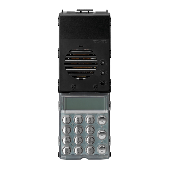
Description Electronic units 13F4 (audio) and 13F7 (video) can be used only in Due Fili Plus systems. They are equipped with an alphanumeric keypad and the video version has a camera with a white LED lighting unit. Electronic units 13F4 and 13F7 can be used as replacements in systems equipped with electronic units art. 12F4, 12F7. For entrance panels 89F4, 89F7 the spare part is functional, not mechanical. - Page 4 Connection of a CCTV type external camera to an audio electronic unit To connect an external CCTV camera to an audio electronic unit (13F4), the electronic unit must be configured as if it were intended for video entryphone use. This type of configuration is accomplished by removing the SA jumper. To perform the operation, raise the alphanumeric keypad (see figure 4), remove the SA jumper, then reinstate the alphanumeric keypad.
- Page 5 Switching on the electronic unit Each time the electronic unit is switched on, the display shows the ani- mation of the Due Fili Plus logo. To skip it, press any key on the numeric You can now run a subset of the configurations of the electronic unit, those keypad.
- Page 6 - There can be three cases: Dial the call code of the desired extension using buttons . Press WXYZ to cancel the operation or to call. When dialling, if is active ID already exists for selection of the “Lock code" (paragraph 1.9), do not utilize as the first button.
-
Page 7: Volume Adjustment
panel at rest, i.e. no calls, self-starting, or configurations in progress. Some sing the button, or make a new one directly by keying in the new code codes can be employed only during certain time bands. See paragraph 5.1. and confirming with . -
Page 8: Parameter Configuration
Parameter configuration Changes are made connecting one electronic unit at a time. In systems with several electronic units, one unit must be identified as a MASTER and the other units as SLAVE units, regardless of model or type (alpha- numeric, buttons, landing). All entrance panels are supplied with the electronic unit set as MASTER (ID = 1). Procedure for accessing parameter configuration mode You have to start with the electronic unit in a state of rest: there must be no calls in progress, no self-starting or anything similar. -
Page 9: Message Language
The following sections describe the possible configurations of the electronic units using the keypad and display. For all of them, to confirm the change in configuration, the first line of the display shows: Message language In the event of parameter error, the display shows a situation similar to this: Entrance panel ID You can go to the next setting by pressing the button, to the previous one with... - Page 10 ID in the range of the (video) door entry units for which some configurations can be made in the electronic unit. They are: remapping in the event of non-sequential numbering, contacts list, enabling use of the lock / F1 / F2, self-starting. Default: 1 Final ID 1.4 - Final ID...
- Page 11 Preferential code Default: 2.0 - Preferential code Preferential code Associates the button with a code for calling an indoor unit or the concierge switchboard, with no need to know the name or number, without needing to key it in and without confirming it with .
- Page 12 Search all Contacts press to confirm. After confirming the operation, wait for completion of the cancellation process. Default: no association. Note: You can use the codes from 201 to 204 [from INITIAL ID + 1000 to INITIAL ID + 1007, from 1001 to 1008 by Contacts name default], for the concierge switchboards.
- Page 13 to confirm the change. Default: 654321 Answer time 2.9 - Answer time This is the interval of time, expressed in seconds, that the electronic unit waits from the end of the call signal until there is an answer from the indoor unit. If there is no response within the "answer time", the electronic unit ends the call. If the indoor unit answers before the set interval elapses, the electronic starts to count the conversation time.
- Page 14 3.8 - Balance THIS adjusts the audio compensation on 16 levels between the input channel and output channel (in order to eliminate Balancing any possible Larsen effect). Press to enable changes to the volume setting. Press the buttons to increase or reduce the volume. Press to confirm the change.
- Page 15 DISPLAY COMMON ACTION BUTTON DIRECT ACTION Sets to default the DIRECT Sets to default the COMMON Entrance panel chime enabling of F2, ie enables them enabling of F2, ie disables them Removes from default the DI- Removes from default the COM- RECT enabling of lock, F1, F2, ie MON enabling of lock, F1, F2, ie disables all...
- Page 16 4.5 - F1 common As for the lock, but for the output F1. F1 common 4.6 - F2 common As for the lock, but for the output F2. 4.7 - Disable slave panel search F2 common This parameter is only present if the entrance panel is the Master or is configured for Horizontal Installation. It can be used to disable the search for Slave electronic units via the Master electronic unit, on start-up or after pressing the RESET button.
-
Page 17: Date / Time Format
4.10 Date / Time format PQRS Clock WXYZ Note: In the case of Horizontal installation, the prefix H indicates a Horizontal electronic unit, while V indicates one of the vertical electronic units of the riser where there is the indoor unit. V15 does not exist, its function is performed by the 69RS. - Page 18 5.4 - Code validity time slots The clock of the electronic units 13F4 and 13F7 allows enabling a certain number of Lock codes, F1 codes, F2 codes described in paragraphs 2.2, 2.3 and 2.4 only at certain times of the day. Time Slot Two time bands are envisaged for the 24-hour period, each with a resolution of 30 minutes.
- Page 19 Schemi di collegamento - Wiring diagrams Schema di collegamento unità elettronica audio o video Wiring diagram for audio or video electronic unit Montante Cable riser C - Unità elettronica audio o video F - Alimentatore di sistema L - Serratura elettrica 12 Vdc P - Comando apriporta X - Cavo twistato C - Audio or video electronic unit...
- Page 20 Schema di collegamento di più targhe video o più targhe video e targhe audio Wiring diagram for multiple video entrance panels or multiple video and audio entrance panels Montante Montante Cable riser Cable riser C - Unità elettroniche video F - Alimentatore di sistema L - Serratura elettrica 12 Vdc P - Comando apriporta X - Cavo twistato...
- Page 21 Variante / Version Unità elettronica con cartello numero civico retroilluminato Electronic unit with backlit house number plate module Montante Cable riser EXT+ EXT- VLED +12V Circuito di illuminazione numero civico. Utilizzare solo circuito fornita nella confezione. House number lighting circuit. Use only circuit provided in the package.
- Page 22 Variante / Version Unità elettronica con moduli pulsanti supplementari (fino a 2 moduli art. 12TS o 1 art. 12TD) Electronic unit with additional button modules (up to 2 modules art. 12TS or 1 module art. 12TD) Montante Cable riser Modulo pulsanti supplementari Additional button module...
- Page 23 Variante / Version Collegamento funzioni ausiliarie F1 e F2 Connection of auxiliary functions F1 and F2 Montante Cable riser F1 - Funzione ausiliaria (Contatto NA - Max 3A 230V) Auxiliary function (N.O. Contact - Max 3A 230V) 1 2 3 4 5 F2 - Funzione ausiliaria (Contatto NA - Max 3A 230V) Auxiliary function (N.O.
- Page 24 Vimar SpA: Viale Vicenza, 14 36063 Marostica VI - Italy Tel. +39 0424 488 600 - Fax (Italia) 0424 488 188 49400632A0 02 1405 Fax (Export) 0424 488 709 VIMAR - Marostica - Italy www.vimar.com...
Need help?
Do you have a question about the Elvox 13F4 and is the answer not in the manual?
Questions and answers