Table of Contents
Advertisement
Quick Links
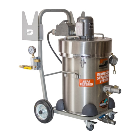
OPERATION AND MAINTENANCE MANUAL
EXPLOSION PROOF / DUST IGNITION PROOF VACUUM CLEANER SYSTEM
ELECTRICALLY OPERATED - IMMERSION SEPARATOR "WET (WATER) MIX"
MODEL 61495 DIVISION 1
EXP1-10 (IT-40L) EX CFE HEPA (2+2)
File number: 090716
Designed and Certified for use in Class I - Group D, T3C
And Class II - Groups E, F & G Hazardous Locations
as defined in the National Electrical Code (NFPA 70)
READ ALL INSTRUCTIONS BEFORE OPERATING,
CLEANING OR SERVICING
IMPORTANT - SAVE THESE INSTRUCTIONS
Page 1 of 24
Advertisement
Table of Contents

Related Manuals for Dynabrade 61495


Summary of Contents for Dynabrade 61495
- Page 1 OPERATION AND MAINTENANCE MANUAL EXPLOSION PROOF / DUST IGNITION PROOF VACUUM CLEANER SYSTEM ELECTRICALLY OPERATED - IMMERSION SEPARATOR "WET (WATER) MIX" MODEL 61495 DIVISION 1 EXP1-10 (IT-40L) EX CFE HEPA (2+2) File number: 090716 Designed and Certified for use in Class I - Group D, T3C And Class II - Groups E, F &...
- Page 2 ROUTINE MAINTENANCE FOR MODELS EXP1-IT - IMMERSION SEPARATOR "WET MIX" • This unit must be filled at all times with water. • This unit must be filled up to the liquid level indicator line shown on the recovery tank. • Do not exceed the below recommended maximum dust recovery capacity. Water required Max.
-
Page 3: Table Of Contents
Table of Contents INSPECTION ............................4 APPLICATIONS ............................4 IMPORTANT SAFETY PRECAUTIONS ....................6 PRE-USAGE INSTRUCTIONS ....................... 7 PRE-CAUTIONS FOR THE RECOVERY OF HAZARDOUS MATERIALS ........... 9 GROUNDING INSTRUCTIONS ......................10 TESTING FOR GROUND CONTINUITY ....................11 FILTRATION SYSTEM ......................... 12 OPERATING INSTRUCTIONS ...................... -
Page 4: Inspection
Process Hazard Analysis. The 61495 / EXP1-IT IMMERSION SEPARATOR "WET (WATER) MIX" is an explosion proof / dust ignition proof vacuum cleaner system designed and certified for use in Class I – Group D, T3C and Class II - Groups E, F &... - Page 5 APPLICATION IN POTENTIALLY EXPLOSIVE ATMOSPHERES IN PRESENCE OF FLAMMABLE GASES, VAPORS OR LIQUIDS The 61495 / EXP1-IT IMMERSION SEPARATOR "WET (WATER) MIX" vacuum cleaner system is designed and certified for use in Class I, Division 1, Group D Hazardous Locations, which representative gas is Propane, and where ignitable concentrations of flammable gases, vapors or liquids can exist all of the time or some of the time under normal operating conditions.
-
Page 6: Important Safety Precautions
3.0 IMPORTANT SAFETY PRECAUTIONS 3.1. DEGASSING VENT A degassing vent is installed on the vacuum cleaner system as a safety feature to prevent gas from building up in the immersion separator. Any gas which may develop escapes through the vent. WARNING: It is the user’s responsibility to conduct a risk assessment as to determine which gas may develop both during... -
Page 7: Pre-Usage Instructions
3.4. IMPORTANT SAFETY PRECAUTIONS REGARD ELECTROSTATIC CHARGES GENERATION When the vacuum cleaner system is used as recommended in this manual it has been determined that no significant or continuous electrostatic charge accumulation, which could act as a potential ignition source, can occur. Nevertheless, it is recommended for safe use not to perform any specific action on the insulating items assembled on the vacuum cleaner system, such as a continuous and intense manual rubbing, which could lead to a significant electrostatic charge accumulation. - Page 8 a. Consult local electric code and authority having jurisdiction before operation. Make sure the electrical installation is compatible with the voltage stated on the nameplate. b. Examine the vacuum cleaner system’s power cable for damage (cracking or ageing) before use. Return to manufacturer for servicing if damaged. Use only the power cable supplied with the unit or one purchased from the manufacturer.
-
Page 9: Pre-Cautions For The Recovery Of Hazardous Materials
5.0 PRE-CAUTIONS FOR THE RECOVERY OF HAZARDOUS MATERIALS WARNING: The vacuum cleaner system not equipped with a CFE HEPA filter is not suitable for the recovery of hazardous materials. DANGER: If the vacuum cleaner system is used to recover toxic or nuisance materials, the following safety precautions must be taken: The vacuum cleaner system must be equipped with a CFE HEPA filter. -
Page 10: Grounding Instructions
6.0 GROUNDING INSTRUCTIONS This vacuum cleaner system must be properly grounded. If it should malfunction or breakdown, grounding provides a path of least resistance for electric current to reduce the risk of electric shock. This vacuum cleaner system is equipped with a cord having an equipment-grounding conductor. -
Page 11: Testing For Ground Continuity
7.0 TESTING FOR GROUND CONTINUITY WARNING: Test the electrical continuity of the vacuum cleaner system before use. This will ensure that any static electricity that is produced while vacuuming will be discharged to ground. WARNING: Use only original replacement parts from the manufacturer or from one of its authorized distributors. -
Page 12: Filtration System
8.0 FILTRATION SYSTEM Page 12 of 24... -
Page 13: Operating Instructions
9.0 OPERATING INSTRUCTIONS WARNING: Turn off the vacuum cleaner system and unplug the power cable before servicing. a. Shut off main air supply and open ball valve on the frame of the vacuum cleaner system to relieve the pressure in the air supply hose. b. - Page 14 c. Disengage the latches and remove the power head from the recovery tank WARNING: Before use the inside of the recovery tank, the suction hose and accessories should be clean and dry d. When used with a conductive recovery bag: Attach the conductive recovery bag to the suction intake inside the recovery tank using clamp.
- Page 15 e. Fill the wet mix immersion separator with water up to the appropriate level f. If liquid foams upon agitation, use a de-foaming agent. Add the prescribed amount of de- foaming agent into the immersion separator in order to prevent foam from entering the powerhead.
- Page 16 h. Connect the airline hose of a suction/air hose to the air outlet placed on the frame of the vacuum cleaner system i. Attach the suction hose of a suction/air hose to the suction intake on the side of immersion separator.
- Page 17 l. Connect the vacuum cleaner to a grounded electrical outlet. m. Open the main air supply and the ball valve on the vacuum cleaner system. n. To turn the vacuum cleaner on, turn switch to the ON position o. Operate the sander/pneumatic tools as required. WARNING: Follow the instructions provided with the sander/pneumatic tool to ensure proper operation.
-
Page 18: Cleaning And Maintenance
10.0 CLEANING AND MAINTENANCE WARNING: Turn off the vacuum cleaner system and unplug the power cable before servicing. a. Shut off main air supply and open ball valve on the frame of the vacuum cleaner system to relieve the pressure in the air supply hoses. b. - Page 19 VERIFICATION OF WATER LEVEL After 5 hours of consecutive use turn off the vacuum cleaner system and verify the water level is still between the indicated minimum and maximum levels. If the water level is below the indicated minimum level adjust by filling the wet mix immersion separator with water up to the appropriate level IMPORTANT: In order to check the level of water the vacuum cleaner system needs...
- Page 20 IMPORTANT: We recommend proceeding with the following maintenance after each use and after a maximum of 8 hours of consecutive use a. Use the drain valve to empty collected material. WARNING: Empty collected material as soon as water reaches the maximum indicated level.
- Page 21 c. Dispose of collection bag when full and replace by a new collection bag d. Clean the recovery tank and remove all remaining material e. Clean hose to remove any accumulated dust, debris or material recovered. WARNING: Be sure to remove any remaining materials after use by rinsing and cleaning the recovery tank, the suction hose and accessories.
-
Page 22: Assembling And Replacing The Cfe Hepa Filter
11.0 ASSEMBLING AND REPLACING THE CFE HEPA FILTER A CFE HEPA filter is designed for filtration of ultra-fine particles. A clogged CFE HEPA filter will reduce the air flow thereby reducing the vacuum’s performance thus requiring replacement. The life of the CFE HEPA filter depends greatly on the use of the vacuum cleaner system. It is recommended the CFE HEPA filter be replaced once a year if the vacuum is used intensively (daily). - Page 23 c. Once the pressure has been relieved close ball valve on the frame of the vacuum cleaner system d. Disengage the latches and remove the power head from the recovery tank. e. Unscrew the hex nut securing the CFE HEPA filter to the underside of the lid. f.
-
Page 24: Motor Maintenance
12.0 MOTOR MAINTENANCE The motor used in this vacuum cleaner system is designed for maintenance free operation and it does not need to be serviced. However, clean regularly the vacuum cleaner system surfaces with a damped cloth to avoid dust accumulation. 13.0 STORAGE It is recommended that the inside of the recovery tank be clean and dry when storing the vacuum cleaner system. - Page 25 EXP1 MODELS CERTIFIED FOR: CLASS I, DIVISION 1, GROUP D T3C AND CLASS II, DIVISION 1, GROUPS E, F & G DYNABRADE EXP1-10 IT-40L 2+2 EX CFE HEPA CSA DYNABRADE EXP1-10 IT-40L 2+2 EX CFE HEPA CSA JANUARY 2019 SHEET 1 OF 7...
- Page 26 EXP1 MODELS CERTIFIED FOR: CLASS I, DIVISION 1, GROUP D T3C AND CLASS II, DIVISION 1, GROUPS E, F & G DYNABRADE EXP1-10 IT-40L 2+2 EX CFE HEPA CSA POWER HEAD DETAIL A DETAIL DETAIL DYNABRADE EXP1-10 IT-40L 2+2 EX CFE HEPA CSA...
- Page 27 EXP1 MODELS CERTIFIED FOR: CLASS I, DIVISION 1, GROUP D T3C AND CLASS II, DIVISION 1, GROUPS E, F & G DYNABRADE EXP1-10 IT-40L 2+2 EX CFE HEPA CSA POWER HEAD PART LIST PART NUMBER ITEM DESCRIPTION 62968 LID W/BRACKET...
- Page 28 EXP1 MODELS CERTIFIED FOR: CLASS I, DIVISION 1, GROUP D T3C AND CLASS II, DIVISION 1, GROUPS E, F & G DYNABRADE EXP1-10 IT-40L 2+2 EX CFE HEPA CSA TANK INCLUDED 9.5'' 7.50'' 1.875'' 2.25'' DETAIL B DETAIL DETAIL DYNABRADE EXP1-10 IT-40L 2+2 EX CFE HEPA CSA...
- Page 29 EXP1 MODELS CERTIFIED FOR: CLASS I, DIVISION 1, GROUP D T3C AND CLASS II, DIVISION 1, GROUPS E, F & G DYNABRADE EXP1-10 IT-40L 2+2 EX CFE HEPA CSA TANK PART LIST ITEM PART NUMBER DESCRIPTION 62942 DRUM W/WHEEL BRACKET...
- Page 30 EXP1 MODELS CERTIFIED FOR: CLASS I, DIVISION 1, GROUP D T3C AND CLASS II, DIVISION 1, GROUPS E, F & G DYNABRADE EXP1-10 IT-40L 2+2 EX CFE HEPA CSA CART 5.50'' 3.50'' 15.50'' .28'' 3.50'' DETAIL TO FIX TANK DYNABRADE EXP1-10 IT-40L 2+2 EX CFE HEPA CSA...
- Page 31 EXP1 MODELS CERTIFIED FOR: CLASS I, DIVISION 1, GROUP D T3C AND CLASS II, DIVISION 1, GROUPS E, F & G DYNABRADE EXP1-10 IT-40L 2+2 EX CFE HEPA CSA CART PART LIST ITEM PART NUMBER DESCRIPTION 62790 CARRIAGE FRAME 62791...
Need help?
Do you have a question about the 61495 and is the answer not in the manual?
Questions and answers