Table of Contents
Advertisement
Quick Links
The Safety Alert Symbol
sonal injury.
Please familiarize yourself with these instructions before
attempting to install or operate this Radiant Heater.
Type RADD Electric
Radiant Heaters
Before Installing:
1. Open carton and remove heater at the place of installation.
Mounting clamps are in parts bag in carton.
2. Check nameplate volt and watt rating against your power sup-
ply voltage and heating requirements of your installation. This
nameplate is located on one end of the heater.
The system designer is responsible for the safety
of this equipment and should install adequate
back-up controls and safety devices with their
electric heating equipment. Where the conse-
quences of failure could result in personal injury or
property damage, back-up controls are essential.
Electric Shock Hazard. Disconnect all power
before installing or servicing heater. Failure to do
so could result in personal injury or property dam-
age. Heater must be installed or serviced by a
qualified person in accordance with the National
Electrical Code, NFPA 70.
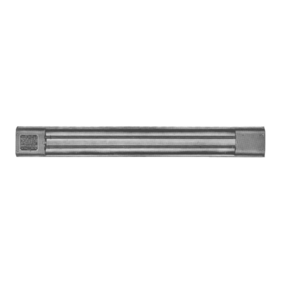
1. These radiant heaters are designed for indoor installation only.
2. Mounting Clamps — Mount heaters by using the mounting
clamp and 3/8" bolt assembly.
Figure 1 — Heater Parts and Dimensions
© 2010 Chromalox, Inc.
Chromalox
Installation, Operation
and
!
is used to indicate a risk of per-
B
A
(Interlocking Connectors
Discontinued)
®
DIVISION
SALES
REFERENCE
DATE
Specifications
Model No.
RADD-2164
RADD-2164V
RADD-3224
RADD-3224V
RADD-3264V
RADD-3264
RADD-4364V
RADD-4364
RADD-5434V
RADD-5434
RADD-5504V
RADD-5504
RADD-6544V
RADD-6544
RADD-6604V
RADD-6604
RADD-7674V
RADD-7674
RADD-7724V
RADD-7724
RADD-8904V
RADD-8904
RADD-7604X10
RADD-7604X13
RADD-7604X9A
RADD-7724X38
INSTALLATION
Clamp assembly may be attached to heater by sliding over end
or by snapping over top of extruded frame section at any point
along its length. (see Fig. 2) For proper heater support, the
maximum distance between clamps must not exceed 48". On
extra-long heaters, more than two clamps are furnished.
3. Mounting Holes — When heaters are mounted adjacent to
each other in the same plane, note that distance between
mounting holes on framing to support heaters will be 3-11/16"
minimum. When heaters are not in the same plane, i.e., set at
an angle to one another, distance between mounting holes in
framing will be either greater or less than 3-11/16".
4. Framing — Where an extensive installation is being made, the
use of continuous slot metal framing manufactured by several
concerns will be of assistance in saving time and money. The
framing is reusable.
4
RADD
SECTION
(Supersedes PG412-9)
161-026681-001
DECEMBER, 2008
A
Volts
kW
Overall Length
120 or 240
1.6
24-3/8
208 or 275
120 or 240
2.2
30-5/8
208 or 275
208 or 275
2.6
35-7/8
240 or 480
208 or 275
3.6
46-5/8
240 or 480
208 or 275
4.3
53-7/8
240 or 480
208 or 275
5.0
61-3/8
240 or 480
208 or 275
5.4
65-7/8
240 or 480
208 or 275
6.0
73-3/4
240 or 480
208 or 275
6.7
79-7/8
240 or 480
208 or 275
7.2
85-3/4
240 or 480
208 or 275
9.0
106
240 or 480
240 or 480
8.0
114-1/8
240 or 480
10
141
240 or 480
11
160-5/8
240 or 480
13
185-5/8
Figure 2
PG412-10
B
Heated Length
16-1/2
22-3/4
28-5/16
38-1/2
45-7/16
53-3/8
58-1/4
65-3/4
72-1/4
78
97-1/2
106
132
150
174
Advertisement
Table of Contents

Related Manuals for Chromalox PG412-10


Summary of Contents for Chromalox PG412-10
- Page 1 1. These radiant heaters are designed for indoor installation only. 2. Mounting Clamps — Mount heaters by using the mounting clamp and 3/8” bolt assembly. Figure 1 — Heater Parts and Dimensions © 2010 Chromalox, Inc. ® Specifications is used to indicate a risk of per- INSTALLATION 3.
- Page 2 5. Reflector Spacer Sheets — Where heaters are not mounted side by side (see Fig. 2), reflector spacer sheets can be used between heaters. These reflector spacer sheets and companion reflectors consisting of an extruded aluminum housing with reflector sheet and mounting clamps are available.
- Page 3 B. Maximum Ambient Temperatures Chromalox Radiant Heaters are not recommended for applica- tions in ambient temperatures exceeding 450°F. Higher ambi- ent temperatures mean shorter heater life.
- Page 4 RENEWAL PARTS IDENTIFICATION PARTS COMMON TO ALL HEATERS Terminal Cover ......306-014405-001 Terminal Cover Clip ......056-014401-002 End Plates .
- Page 5 Watts Model Element Number Volts Element Model Number RTU-2083A-120V (2) RTU-2083AV-208V (2) RADD-2164 RTU-2083A-240V (2) RTU-2083AV-275V (2) RTU-3113A-120V (2) RTU-3113AV-208V (2) RADD-3224 1100 RTU-3113A-240V (2) RTU-3113AV-275V (2) RTU-3133AV-208V (2) RTU-3133A-240V (2) RADD-3264 1300 RTU-3133AV-275V (2) RTU-3133A-480V (2) RTU-4183AV-208V (2) RTU-4183A-240V (2) RADD-4364 1800 RTU-4183AV-275V (2)
- Page 6 Limited Warranty: Please refer to the Chromalox limited warranty applicable to this product at http://www.chromalox.com/customer-service/policies/termsofsale.aspx. 2150 N. RULON WHITE BLVD., OGDEN, UT 84404 Phone: 1-800-368-2493 www.chromalox.com...
Need help?
Do you have a question about the PG412-10 and is the answer not in the manual?
Questions and answers