Table of Contents
Advertisement
Quick Links
NF4 Ultra-A9
FCC Information and Copyright
This equipment has been tes ted and found to comply with the limits of a Class
B digital devic e, purs uant to Part 15 of the FCC Rules . T hese limits are designed
to provide reasonable protec tion against harmful interference in a residential
installation. T his equipment generates , uses and can radiate radio frequency
energy and, if not ins talled and used in accordance with the instructions , may
cause harmful interference to radio communications . There is no guarantee
that interference will not occur in a particular ins tallation.
The vendor makes no representations or warranties with respec t to the
contents here and s pecially disclaims any implied warranties of merchantability
or fitness for any purpose. Further the vendor reserves the right to revise this
publication and to make c hanges to the c ontents here without obligation to
notify any party beforehand.
D uplication of this publication, in part or in whole, is not allowed without first
obtaining the vendor's approval in writing.
The content of this user's manual is subject to be c hanged without notice and
we will not be res ponsible for any mis takes found in this user's manual. All the
brand and produc t names are trademarks of their respec tive companies .
i
Advertisement
Chapters
Table of Contents

Subscribe to Our Youtube Channel
Related Manuals for Biostar NF4 Ultra-A9


Summary of Contents for Biostar NF4 Ultra-A9
- Page 1 NF4 Ultra-A9 FCC Information and Copyright This equipment has been tes ted and found to comply with the limits of a Class B digital devic e, purs uant to Part 15 of the FCC Rules . T hese limits are designed to provide reasonable protec tion against harmful interference in a residential installation.
-
Page 2: Table Of Contents
Table of Contents Chapter 1: Introduction ............1 Motherboard Features ............ 1 Package Checklist............6 Layout & Components............ 7 Chapter 2: Hardware Installation ..........8 Central Processing Unit (CPU)........8 Fan Headers..............10 Memory Modules Installation ........11 Connectors, & Slots ............12 Chapter 3: Headers & Jumpers Setup.......13 How to setup Jumpers ...........13 Detail Settings...............13 Chapter 4: Useful Help............19... -
Page 3: Chapter 1: Introduction
NF4 Ultra-A9 CHAPTER 1: INTRODUCTION OTHERBOARD EATURES A. Hardware Supports Socket 939. Supports AMD Athlon 64 FX processo r. Supports AMD Athlon 64 processor. Supports AMD Sempron processo r. AMD 64 architecture enables simultaneous 32 and 64 bit computing. Supports HyperTransport Technology. - Page 4 NF4 Ultra-A9 Dimensions ATX Form Factor: 23.4cm (W) x 29.35cm (L) Main Memory Supports Dual Channel DDR. Supports 8 banks in total. Supports DDR333 and DDR400. Maximum memory size is 4GB. DIMM Socket Total Memory DDR Module Location Size (MB)
- Page 5 NF4 Ultra-A9 Slots Three 32bit PCI bus master slots. Two PCI-Express x1 slots: PCI Express 1.0a compliant. Bandwidth 250MB/s per direction. One PCI-Express x16 slot. PCI Express 1.0a compliant. Maximum theoretical realized bandwidth of 4GB/s simultaneously per direction, for an aggregate of 8GB/s totally.
- Page 6 NF4 Ultra-A9 Gigabit Ethernet LAN NVIDIA Gigabit MAC + VITESSE Gigabit PHY VSC8201. Supports 10 Mb/s, 100 Mb/s and 1Gb/s auto-negotiation. Half/Full duplex capability. Supports personal Firewall setup. Supports ACPI power management. Supports NVIDIA StreamThru technology Isochronous controller paired with Hyper Transport results...
- Page 7 NF4 Ultra-A9 Internal On-board Connectors and Headers 1 audio-out header supports audio-out facilities. 1 front panel header supports front panel facilities. 1 CD-in connector supports CD-ROM audio-in function. 1 SPDIF-out connector supports digital audio-out function. 1 SPDIF-in connector supports digital audio-in function (optional).
-
Page 8: Package Checklist
NF4 Ultra-A9 3 audio ports support 6 channels audio-out facilities (with ALC655, optional). Con nector 1394 Port PS/2 (optional) Mo use Printer Port Line -in/Rear Line -out MIC-in/ PS/2 Cente r/ USB *2 USB *2 Keybo ard COM1 COM2 Le ft (optional) B. -
Page 9: Layout & Components
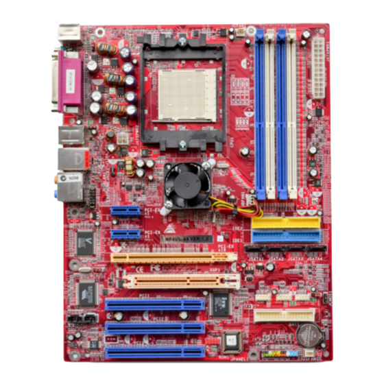
NF4 Ultra-A9 & C AYOUT OMPONENTS JCFAN1 JKBMS1 JATXPWR1 J KBM SV1 JCOM1 CPU1 JCOM 2 (op ti o nal) J1394_USBV1 JATXPWR2 J1394_USB1 JUSBLAN1 nForce4 E A RPHONEJACK1 CK8-04 JAUDI O2 Ultra J NBF AN1 PCI-EX x1 P EX1-2 IDE2... -
Page 10: Chapter 2: Hardware Installation
NF4 Ultra-A9 CHAPTER 2: HARDWARE INSTALLATION (CPU) ENTRAL ROCESSING Step 1: Remove the socket protection cap. Step 2: Pull the lever sideways away from the socket and then raise the lever up to a 90-degree angle. - Page 11 NF4 Ultra-A9 Step 3: Look for the black cut edge on socket, and the white dot on CPU should point forwards this black cut edge. The CPU will fit only in the correct orientation. Step 4: Hold the CPU down firmly, and then close the lever to complete the installation.
-
Page 12: Fan Headers
NF4 Ultra-A9 EADERS CPU FAN Powe r Heade r: JCFAN1 Assignment Ground +12V FAN RPM rate sense System Fan Power Header: JSFAN1 Assignment Ground +12V FAN RPM rate sense North Bridge Fan Power Header: JNBFAN1 Assignment Ground +12V FAN RPM rate sense... -
Page 13: Memory Modules Installation
NF4 Ultra-A9 EMORY ODULES NSTALLATION 2.2.1 DDR M odule installation 1. Unlock a DIMM slot by pressing the retaining clips outward. Align a DIMM on the slot such that the notch on the DIMM matches the break on the Slot. -
Page 14: Connectors, & Slots
PC. After PC restarts, the system will automatically set the AGP VGA card as the graphics adapter. 2. Re-install your operating system to ensure the AGP VGA card function can be used. Note: Please go to “http://www.biostar.com.tw” for more detailed information about XGP compatible AGP cards. -
Page 15: Chapter 3: Headers & Jumpers Setup
NF4 Ultra-A9 CHAPTER 3: HEADERS & JUMPERS SETUP OW TO SETUP UMPERS The illustration shows how to set up jumpers. When the jumper cap is placed on pins, the jumper is “close”, if not, that means the jumper is “open”. - Page 16 NF4 Ultra-A9 Powe r Source He ade rs for USB Ports: J1394_USBV1/JUSBV1 Assignment Description J1394_USBV1: +5V for USB ports at J1394_USB1 and JUSBLAN1. JUSBV1: +5V for front USB headers Pin 1-2 close (JUSB1/JUSB2/JUSB3). J1394_USBV1: USB ports at J1394_USB1 and JUSBLAN1 are +5V standby powered with +5V standby v oltage.
- Page 17 NF4 Ultra-A9 Front Panel Audio-out Heade r: JAUDIO2 This connector will allow user to connect with the front audio out put headers on the PC case. It will disable the output on back panel audio connectors. With ALC850 Audio Sound Codec:...
- Page 18 NF4 Ultra-A9 Digital Audio-out Connector: JSPDIF_O UT This connector will allow user to connect the PCI bracket SPDIF output header. Assignment SPDIF OUT JSPDIF_OUT Ground Digital Audio-in Connector: JSPDIF_IN1 (optional) This connector will allow user to connect the PCI bracket SPDIF output header.
- Page 19 NF4 Ultra-A9 He ade r for Front Panel Facilities: JPANEL1 This 24-pin connector includes Power-on, Reset, HDD LED, Power LED, Sleep button, speaker and IrDA Connection. It allows user to connect the PC case’s front panel switch functions. JPANEL1 Assignment...
- Page 20 NF4 Ultra-A9 Close CMOS Heade r: JCMOS1 By placing the jumper on pin2-3, it allows user to restore the BIOS safe setting and the CMOS data, please carefully follow the procedures to avoid damaging the motherboard. JCMOS1 Assignment Normal Operation (Def ault).
-
Page 21: Chapter 4: Useful Help
NF4 Ultra-A9 CHAPTER 4: USEFUL HELP BIOS B WARD Beep Sound Meaning One long beep followed by two short Video card not found or v ideo card beeps memory bad High-low siren sound CPU overheated System will shut down automatically... -
Page 22: Chapter 5: Nvidia Raid Functions
NF4 Ultra-A9 CHAPTER 5: NVIDIA RAID FUNCTIONS PERATION YSTEM Windows XP home Edition Windows XP Professional Edition Windows 2000 Professional RRAYS NVRAID supports the following types of RAID arrays: RAID 0: RAID 0 defines a disk striping scheme that improves disk read and writes times for many applications. -
Page 23: How Raid Works
NF4 Ultra-A9 RAID W ORKS RAID 0: The controller “ stripes” data across multiple drives in a RAID 0 array system. It breaks up a large file into smaller blocks and performs disk reads and writes across multiple drives in parallel. T he size of each block is determined by the strip size parameter, which you set during the creation of the RAID set based on the system environment. - Page 24 NF4 Ultra-A9 RAID 1: Every read and write is actually carried out in parallel across 2 disk drives in a RAID 1 array system. The mirrored (backup) copy of the data can reside on the same disk or on a second redundant drive in the array.
- Page 25 NF4 Ultra-A9 RAID 0+1: RAID 0 drives can be mirrored suing RAID 1 techniques. Resulting in a RAID 0+1 solution for improved performance plus resiliency. nVIDIA nForce 4 CK8-04 Ultra Bl ock 1 Block 2 Block 1 Block 2 Block 3...
- Page 26 NF4 Ultra-A9 Spanning (JBOD): JBOD stands for “ Just a Bunch of Disks”. Each drive is accessed as if it were on a standard SCSI host bus adapter. T his is useful when a single drive configuration is needed, but it offers no speed improvement or fault tolerance.
-
Page 27: Chapter 6: Warpspeeder
NF4 Ultra-A9 CHAPTER 6: WARPSPEEDER™ NTRODUCTION [WarpSpeeder™], a new powerful control utility, features three user-friendly functions including Overclock Manager, Overvoltage Manager, and Hardware Monitor. With the Overclock Manager, users can easily adjust the frequency they prefer or they can get the best CPU performance with just one click. The Overvoltage Manager, on the other hand, helps to power up CPU core voltage and Memory voltage. -
Page 28: Installation
NF4 Ultra-A9 NSTALLATION 1. Execute the setup execution file, and then the following dialog will pop up. Please click “Next” button and follow the default procedure to install. 2. When you see the following dialog in setup procedure, it means setup is completed. -
Page 29: Warpspeeder™] Includes 1 Tray Icon And 5 Panels
NF4 Ultra-A9 ™] PEEDER INCLUDES TRAY ICON AND PANELS 1. Tray Icon: Whenever the Tray Icon utility is launched, it will display a little tray icon on the right side of Windows Taskbar. This utility is responsible for conveniently invoking [WarpSpeeder™] Utility. - Page 30 NF4 Ultra-A9 2. Main Panel If you click the tray icon, [WarpSpeeder™] utility will be invoked. Please refer to the following figure; the utility’s first window you will see is Main Panel. Main Panel contains fe ature s as follows: Display the CPU Speed, CPU external clock, Memory clock, AGP clock, and PCI clock information.
- Page 31 NF4 Ultra-A9 3. Voltage Panel Click the Voltage button in Main Panel, the button will be highlighted and the Voltage Panel will slide out to up as the following figure. In this panel, you can decide to increase CPU core voltage and Memory voltage or not.
- Page 32 NF4 Ultra-A9 4. Overclock Panel Click the Overclock button in Main Panel, the button will be highlighted and the Overclock Panel will slide out to left as the following figure. O ve rclock Panel contains the these features: “–3MHz button”, “-1MHz button”, “+1MHz button”, and “+3MHz button”: provide user the ability to do real-time overclock...
- Page 33 NF4 Ultra-A9 “Auto-overclock button”: User can click this button and [WarpSpeeder™] will set the best and stable performance and frequency automatically. [WarpSpeeder™] utility will execute a series of testing until system fail. Then system will do fail-safe reboot by using Watchdog function. After reboot, the [WarpSpeeder™] utility will restore to the hardware default...
- Page 34 NF4 Ultra-A9 6. About Panel Click the “about” button in Main Panel, the button will be highlighted and the About Panel will slide out to up as the following figure. In this panel, you can get model name and detail information in hints of all the chipset that are related to overclocking.
- Page 35 NF4 Ultra-A9 Note : Because the overclock, overvoltage, and hardware monitor features are controlled by several separate chipset, [WarpSpeeder™] divide these features to separate panels. If one chipset is not on board, the correlative button in Main panel will be disabled, but will not interfere other panels’...
- Page 36 NF4 Ultra-A9 BIOS Setup BIOS Setup..................1 1 Main Menu ....................... 3 2 Standard CMOS Features................... 6 3 Advanced BIOS Features ................... 9 4 Advanced Chipset Features................12 5 Integrated Peripherals ..................15 6 Power Management Setup................21 7 PnP/PCI Configurations ................... 24 8 PC Health Status .....................
-
Page 37: Bios Setup
NF4 Ultra-A9 BIOS Setup Introduction This manual discussed Award™ Setup program built into the ROM BIOS. The Setup program allows users to modify the basic system configuration. This special information is then stored in battery-backed RAM so that it retains the Setup information when the power is turned off. - Page 38 NF4 Ultra-A9 PCI Bus Support This AWARD BIOS also supports Version 2.1 of the Intel PCI (Peripheral Component Interconnect) local bus specification. DRAM Support DDR SDRAM (Double Data Rate Synchronous DRAM) are supported. Supported CPUs This AWARD BIOS supports the AMD CPU.
-
Page 39: Main Menu
NF4 Ultra-A9 1 Main Menu Once you enter Award BIOS™ CMOS Setup Utility, the Main Menu will appear on the screen. The Main Menu allows you to select from several setup functions. Use the arrow keys to select among the items and press <Enter> to accept and enter the sub-menu. - Page 40 NF4 Ultra-A9 Power Management Setup This submenu allows you to configure the power management features. PnP/PCI Configurations This submenu allows you to configure certain “Plug and Play” and PCI options. PC Health Status This submenu allows you to monitor the hardware of your system.
- Page 41 NF4 Ultra-A9 Set User Password If the Supervisor Password is not set, then the User Password will function in the same way as the Supervisor Password. If the Supervisor Password is set and the User Password is set, the “User” will only be able to view configurations but will not be able to change them.
-
Page 42: Standard Cmos Features
NF4 Ultra-A9 2 Standard CMOS Features The items in Standard CMOS Setup Menu are divided into 10 categories. Each category includes no, one or more than one setup items. Use the arrow keys to highlight the item and then use the<PgUp> or <PgDn> keys to select the value you want in each item. - Page 43 NF4 Ultra-A9 Main Menu Selections This table shows the selections that you can make on the Main Menu. Item Options Description Date mm : dd : yy Set the system date. Note that the ‘Day’ automatically changes when you set the date.
- Page 44 NF4 Ultra-A9 Item Options Description Halt On All Errors Select the situation in which No Errors you want the BIOS to stop All, but Keyboard the POST process and All, but Diskette notify you. All, but Disk/ Key Base Memory...
-
Page 45: Advanced Bios Features
NF4 Ultra-A9 3 Advanced BIOS Features Figure 3. Advanced BIOS Setup Virus Warning This option allows you to choose the Virus Warning feature that is used to protect the IDE Hard Disk boot sector. If this function is enabled and an attempt is made to write to the boot sector, BIOS will display a warning message on the screen and sound an alarm beep. - Page 46 NF4 Ultra-A9 Typematic Rate Setting When a key is held down, the keystroke will repeat at a rate determined by the keyboard controller. When enabled, the typematic rate and typematic delay can be configured. Disabled (default) Enabled Typematic Rate (Chars/Sec) Sets the rate at which a keystroke is repeated when you hold the key down.
- Page 47 NF4 Ultra-A9 Cache Setup These BIOS attempt to load the operating system from the device in the sequence selected in these items. CPU Internal Cache Depending on the CPU/chipset in use, you may be able to increase memory access time with this option.
-
Page 48: Advanced Chipset Features
NF4 Ultra-A9 4 Advanced Chipset Features This submenu allows you to configure the specific features of the chipset installed on your system. This chipset manage bus speeds and access to system memory resources, such as DRAM. It also coordinates communications with the PCI bus. The default settings that came with your system have been optimized and therefore should not be changed unless you are suspicious that the settings have been changed incorrectly. - Page 49 NF4 Ultra-A9 DRAM Configuration CAS# Latency This field specify the cas# latency, i.e. cas# to read data valid. The Choices: CL=2.5 (Default), CL=3.0, CL=2.0 Min RAS# active time (tRAS) This field specifies the minimum RAS# active time. Typically -45-60 Nsec.
- Page 50 NF4 Ultra-A9 PCIE Spread Spectrum SATA This item allows you to disable \ enable the spread spectrum function. The choices: Disabled (default), enable. SSE/SSE2 Instructions The choices:Enabled (default), Disabled. System BIOS Cacheable Selecting the “Disabled ” option allows caching of the system BIOS ROM at F0000h-FFFFFh which can improve system performance.
-
Page 51: Integrated Peripherals
NF4 Ultra-A9 5 Integrated Peripherals Figure 5. Integrated Peripherals IDE Function Setup If you highlight the literal “Press Enter” next to the “IDE Function Setup” label and then press the enter key, it will take you a submenu with the following options:... - Page 52 NF4 Ultra-A9 Primary / Secondary /Master / Slave PIO The IDE PIO (Programmed Input / Output) fields let you set a PIO mode (0-4) for each of the IDE devices that the onboard IDE interface supports. Modes 0 to 4 will increased performance progressively.
- Page 53 NF4 Ultra-A9 RAID Configuration RAID Enable The choices: Disabled (default), enable. ONBOARD DEVICE OnChip USB This option should be enabled if your system has a USB installed on the system board. You will need to disable this feature if you add a higher performance controller.
- Page 54 NF4 Ultra-A9 USB keyboard Support Enables support for USB attached keyboard. The Choices: Disabled (default), Enabled USB Mouse Support Enables support for USB attached mouse. The Choices: Disabled (default), Enabled AC97 Audio This option allows you to control the onboard AC97 audio.
- Page 55 NF4 Ultra-A9 ONBOARD IO/Address Onboard FDC Controller Select Enabled if your system has a floppy disk controller (FDC) installed on the system board and you wish to use it. If install and FDC or the system has no floppy drive, select Disabled in this field.
- Page 56 NF4 Ultra-A9 Onboard Parallel Port This item allows you to determine access onboard parallel port controller with which I/O Address. The Choices: 378/IRQ7 (default), 278/IRQ5, 3BC/IRQ7, Disabled. Parallel Port Mode The default value is SPP. The Choices: SPP(default) Using Parallel port as Standard Printer Port.
-
Page 57: Power Management Setup
NF4 Ultra-A9 6 Power Management Setup The Power Management Setup Menu allows you to configure your system to utilize energy conservation and power up/power down features. Figure 6. Power Management Setup ACPI function This item displays the status of the Advanced Configuration and Power Management (ACPI). - Page 58 NF4 Ultra-A9 HDD Power Down = 15 min Max. Power Saving Maximum power management only available for sl CPU’s. Suspend Mode = 1 min. HDD Power Down = 1 min. User Define (default) Allows you to set each mode individually.
- Page 59 NF4 Ultra-A9 USB Resume from S3 The Choices: Disabled (default), Enabled. Power-On by Alarm When you select Enabled, an alarm returns the system to Full ON state. The Choices: Disabled (default), Enabled. POWER After PWR-Fail This setting specifies whether your system will reboot after a power fail or interrupts occurs.
-
Page 60: Pnp/Pci Configurations
NF4 Ultra-A9 7 PnP/PCI Configurations This section describes configuring the PCI bus system. PCI, or Personal Computer Interconnect, is a system which allows I/O devices to operate at speeds nearing the speed of the CPU itself uses when communicating with its own special components. This section covers some very technical items and it is strongly recommended that only experienced users should make any changes to the default settings. - Page 61 NF4 Ultra-A9 IRQ-3 assigned to PCI Device IRQ-4 assigned to PCI Device IRQ-5 assigned to PCI Device IRQ-7 assigned to PCI Device IRQ-9 assigned to PCI Device IRQ-10 assigned to PCI Device IRQ-11 assigned to PCI Device IRQ-12 assigned to...
-
Page 62: Pc Health Status
NF4 Ultra-A9 8 PC Health Status Figure 8. PC Health Status Chassis Open Warning This item allows you to enable or disable Chassis Open Warning beep. The Choices: Disabled (Default), Enabled. Shutdown Temperature This item allows you to set up the CPU shutdown Temperature. This item only effective under Windows 98 ACPI mode. - Page 63 NF4 Ultra-A9 Current CPU FAN Speed This field displays the current speed of CPU fan. Current SYS FAN Speed This field displays the current speed SYSTEM fan.
-
Page 64: Frequency/Voltage Control
NF4 Ultra-A9 9 Frequency/Voltage Control Figure 8. PC Health Status Hammer Vid Control This item allows you to set different CPU frequency. The Choices: StartUp (default), and other choices from 800Mhz to 5000Mhz. Hammer Fid Control This item allows you to set different CPU voltage.
Need help?
Do you have a question about the NF4 Ultra-A9 and is the answer not in the manual?
Questions and answers