Table of Contents
Advertisement
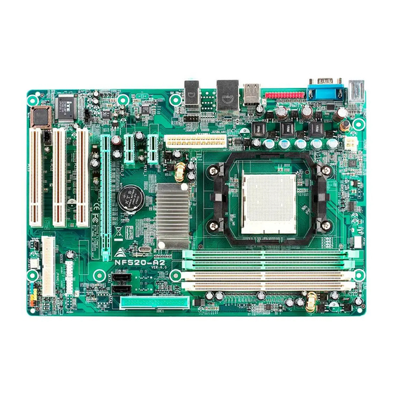
NF560-A2G/NF520-A2G Setup Manual
FCC Information and Copyright
This equipment has been tes ted and found to comply with the limits of a Class
B digital devic e, purs uant to Part 15 of the FCC Rules . T hese limits are designed
to provide reasonable protec tion against harmful interference in a residential
installation. T his equipment generates , uses , and c an radiate radio frequency
energy and, if not ins talled and used in accordance with the instructions , may
cause harmful interference to radio communications . There is no guarantee
that interference will not occur in a particular ins tallation.
The vendor makes no representations or warranties with respec t to the
contents here and s pecially disclaims any implied warranties of merchantability
or fitness for any purpose. Further the vendor reserves the right to revise this
publication and to make c hanges to the c ontents here without obligation to
notify any party beforehand.
D uplication of this publication, in part or in whole, is not allowed without first
obtaining the vendor's approval in writing.
The content of this user's manual is subject to be c hanged without notice and
we will not be res ponsible for any mis takes found in this user's manual. All the
brand and produc t names are trademarks of their respec tive companies .
Advertisement
Chapters
Table of Contents


Need help?
Do you have a question about the NF560-A2G and is the answer not in the manual?
Questions and answers