Table of Contents
Advertisement
Available languages
Available languages
Quick Links
All manuals and user guides at all-guides.com
NF61S-M2 TE Setup Manual
FCC Information and Copyright
This equipment has been tes ted and found to comply with the limits of a Class
B digital devic e, purs uant to Part 15 of the FCC Rules . T hese limits are designed
to provide reasonable protec tion against harmful interference in a residential
installation. T his equipment generates , uses , and c an radiate radio frequency
energy and, if not ins talled and used in accordance with the instructions , may
cause harmful interference to radio communications . There is no guarantee
that interference will not occur in a particular ins tallation.
The vendor makes no representations or warranties with respec t to the
contents here and s pecially disclaims any implied warranties of merchantability
or fitness for any purpose. Further the vendor reserves the right to revise this
publication and to make c hanges to the c ontents here without obligation to
notify any party beforehand.
D uplication of this publication, in part or in whole, is not allowed without first
obtaining the vendor's approval in writing.
The content of this user's manual is subject to be c hanged without notice and
we will not be res ponsible for any mis takes found in this user's manual. All the
brand and produc t names are trademarks of their respec tive companies .
Advertisement
Table of Contents

Related Manuals for Biostar NF61S-M2 TE


Summary of Contents for Biostar NF61S-M2 TE
- Page 1 All manuals and user guides at all-guides.com NF61S-M2 TE Setup Manual FCC Information and Copyright This equipment has been tes ted and found to comply with the limits of a Class B digital devic e, purs uant to Part 15 of the FCC Rules . T hese limits are designed to provide reasonable protec tion against harmful interference in a residential installation.
-
Page 2: Table Of Contents
All manuals and user guides at all-guides.com Table of Contents Chapter 1: Introduction.............1 Before You Start..............1 Package Checklist..............1 Motherboard Features............2 Rear Panel Connectors............3 Motherboard Layout ............4 Chapter 2: Hardware Installation........5 Installing Central Processing Unit (CPU)........ 5 FAN Headers................ -
Page 3: Chapter 1: Introduction
All manuals and user guides at all-guides.com NF61S-M2 TE CHAPTER 1: INTRODUCTION EFORE T ART Thank you for choosing our product. Before you start installing the motherboard, please make sure you follow the instructions below: Prepare a dry and stable work ing environment with sufficient lighting. -
Page 4: Motherboard Features
All manuals and user guides at all-guides.com Motherboard Manual OT HERBOARD EAT URES SPEC Socket AM2 AMD 64 Architecture enables 32 and 64 bit AMD Athlon 64 / Athlon 64 FX / Athlon 64 X2 computing / Sempron processors Supports Hyper Transport and Cool=n=Quiet Supports up to 1GHz Bandwidth Support HyperTransport Chipset... -
Page 5: Rear Panel Connectors
Board Size 190 mm (W) x 244 mm (L) Micro ATX Size Board Special RAID 0 / 1 support Features Biostar Reserves the right to add or remove support OS Support Windows 2000 / XP / VISTA for any OS With or without notice. ANEL ONNECT ORS... -
Page 6: Motherboard Layout
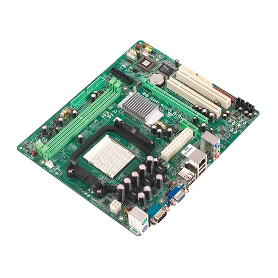
All manuals and user guides at all-guides.com Motherboard Manual OT HERBOARD AYOUT JCFAN1 JKBMS1 JATXPWR2 JUSB1 JATXPW R1 JUSBLAN1 JAUDIO1 GeForce JCDIN1 6100-405 JAUDIOF1 PEX1_1 SATA1 SATA2 PEX16_1 BIOS JCMOS1 BAT1 PCI1 Super I/O PCI2 Codec JSPDIF_OUT1 JPRNT1 JUSB2 JUSB3 JPANEL1 FDD1 JSFAN1... -
Page 7: Chapter 2: Hardware Installation
All manuals and user guides at all-guides.com NF61S-M2 TE CHAPTER 2: HARDWARE INSTALLATION (CPU) NST ALLING ENT RAL ROCESSING Step 1: Remove the socket protection cap. Step 2: Pull the lever toward direction A from the socket and then raise the lever up to a 90-degree angle. - Page 8 All manuals and user guides at all-guides.com Motherboard Manual Step 4: Hold the CPU down firmly, and then close the lever toward direct B to complete the installation. Step 5: Put the CPU Fan on the CPU and buckle it. Connect the CPU FAN power cable to the JCFAN1.
-
Page 9: Fan Headers
All manuals and user guides at all-guides.com NF61S-M2 TE FAN H EADERS These fan headers support cooling-fans built in the computer. The fan cable and connector may be different according to the fan manufacturer. Connect the fan cable to the connector while matching the black wire to pin#1. -
Page 10: Installing System Memory
All manuals and user guides at all-guides.com Motherboard Manual NST ALLING YST EM EMORY A. Memory Modules Unlock a DIMM slot by pressing the retaining clips outward. Align a DIMM on the slot such that the notch on the DIMM matches the break on the Slot. - Page 11 All manuals and user guides at all-guides.com NF61S-M2 TE B. Memory Capacity DIMM Socket DDR Module Total Memory Size Location DIMMA1 256MB/512MB/1GB/2GB *1 Max memory 4GB. DIMMB1 256MB/512MB/1GB/2GB *1 C. Dual Channel Memory installation To trigger the Dual Channel f unction of the motherboard, the memory module must meet the following requirements: Install memory module of the same density in pair, shown in the following table.
-
Page 12: Connectors And Slots
All manuals and user guides at all-guides.com Motherboard Manual 2.4 C ONNECT ORS AND LOT S FDD1: Floppy Disk Connector The motherboard prov ides a standard floppy disk connector that supports 360K, 720K, 1.2M, 1.44M and 2.88M floppy disk ty pes. This connector supports the prov ided f loppy drive ribbon cables. - Page 13 All manuals and user guides at all-guides.com NF61S-M2 TE PEX1_1: PCI-Express x1 Slot PCI-Express 1.0a compliant. Data transf er bandwidth up to 250MB/s per direction; 500MB/s in total. PCI-Express supports a raw bit-rate of 2.5Gb/s on the data pins. 2X bandwidth ov er the traditional PCI architecture.
-
Page 14: Chapter 3: Headers & Jumpers Setup
All manuals and user guides at all-guides.com Motherboard Manual CHAPTER 3: HEADERS & JUMPERS SETUP OW T O ET UP UMPERS The illustration shows how to set up jumpers. When the jumper cap is placed on pins, the jumper is “close”, if not, that means the jumper is “open”. - Page 15 All manuals and user guides at all-guides.com NF61S-M2 TE JATXPWR1: ATX Power Source Connector This connector allows user to connect 24-pin power connector on the ATX power supply. Assignment Assignment +3.3V +3.3V -12V +3.3V Ground Ground PS_ON Ground Ground Ground...
-
Page 16: Sata1 Sata2
All manuals and user guides at all-guides.com Motherboard Manual JUSB2/JUSB3: Headers for USB 2.0 Ports at Front Panel This header allows user to connect additional USB cable on the PC f ront panel, and also can be connected with internal USB devices, like USB card reader. Assignment +5V (fused) +5V (fused) - Page 17 All manuals and user guides at all-guides.com NF61S-M2 TE JCDIN1: CD-RO M Audio-in Connector This connector allows user to connect the audio source f rom the v ariaty dev ices, like CD-ROM, DVD-ROM, PCI sound card, PCI TV turner card etc.
- Page 18 All manuals and user guides at all-guides.com Motherboard Manual J1: Power Source Header for PS/2 Keyboard and Mouse Pin 1-2 close +5V for PS/2 keyboard and mouse. Pin 2-3 close PS/2 keyboard and mouse are powered by +5V standby voltage. Note: In order to support this func tion “Power-on s ystem via keyboar d and mouse”, “J 1”...
- Page 19 All manuals and user guides at all-guides.com NF61S-M2 TE JSPDIF_O UT1: Digital Audio-out Connector This connector allows user to connect the PCI bracket SPDIF output header. Assignment SPDIF_OUT Ground JPRNT1: Printer Port Connector This header allows you to connector printer on the PC.
-
Page 20: Chapter 4: Raid Functions
All manuals and user guides at all-guides.com Motherboard Manual CHAPTER 4: RAID FUNCTIONS PERAT ION YST EM Supports Windows XP Home/Prof essional Edition, and Windows 2000 Professional. 4.2 R RRAYS RAID supports the following types of RAID arrays: RAID 0: RAID 0 defines a disk striping scheme that improves disk read and write times for many applications. - Page 21 All manuals and user guides at all-guides.com NF61S-M2 TE RAID 1: Every read and write is actually carried out in parallel across 2 disk drives in a RAID 1 array system. The mirrored (backup) copy of the data can reside on the same disk or on a second redundant drive in the array.
-
Page 22: Chapter 5: Useful Help
All manuals and user guides at all-guides.com Motherboard Manual CHAPTER 5: USEFUL HELP RIVER NST ALLAT ION OT E After you installed your operating system, please insert the Fully Setup Driver CD into your optical drive and install the driver for better system performance. -
Page 23: Award Bios Beep Code
All manuals and user guides at all-guides.com NF61S-M2 TE BIOS B WARD Beep Sound Meaning One long beep followed by two short Video card not found or v ideo card beeps memory bad High-low siren sound CPU overheated System will shut down automatically... -
Page 24: Troubleshooting
All manuals and user guides at all-guides.com Motherboard Manual 5.4 T ROUBLESHOOT ING Probable Solution No power to the system at all Make sure power cable is Power light don’t illuminate, f an securely plugged in. inside power supply does not turn Replace cable. -
Page 25: Chapter 6: Warpspeeder™ Iii
All manuals and user guides at all-guides.com NF61S-M2 TE WARPSPEEDER™ III CHAPTER 6: NT RODUCT ION [WarpSpeeder™ III], a new powerful control utility, features three user-friendly functions including Overclock Manager, Overvoltage Manager, and Hardware Monitor. With the Overclock Manager, users can easily adjust the frequency they prefer or they can get the best CPU performance with just one click. -
Page 26: Installation
All manuals and user guides at all-guides.com Motherboard Manual 6.3 I NST ALLAT ION 1. Execute the setup execution file, and then the following dialog will pop up. Please click “Next” button and follow the default procedure to install. 2. When you see the following dialog in setup procedure, it means setup is completed. -
Page 27: Warpspeeder™ Iii
All manuals and user guides at all-guides.com NF61S-M2 TE 6.4 W ™ III PEEDER 1. Desktop Icon After the [WarpSpeeder™ III] has been installed, a [WarpSpeeder™ III] icon will appear on the desktop, just like the icon shown below. Now you can launch the [WarpSpeeder™ III] utility simply by double-clicking the desktop icon. - Page 28 All manuals and user guides at all-guides.com Motherboard Manual 3. Overclock/Overvoltage Panel Click the Overclock/Overvoltage button in the Main Panel, the button will be highlighted and the Overclock/Overvoltage Panel will show up as the following figure. As you can see, the Overclock Panel is on the right side, and the Overvoltage Panel is on the left side.
- Page 29 All manuals and user guides at all-guides.com NF61S-M2 TE O verclock Panel contains these features: a. “Auto-Overclock”: User can click this button and [WarpSpeeder™ III] will set the best and stable performance and frequency automatically. A warning dialog as below will show up to notify you that the system may become unstable, click on “OK”...
- Page 30 All manuals and user guides at all-guides.com Motherboard Manual O vervoltage Panel contains these features: a. “CPU Voltage”: This function allows user to adjust CPU voltage. Click on “+” to increase or “-“ to decrease the CPU voltage. b. “Memory Voltage”: This function allows user to adjust Memory voltage.
- Page 31 All manuals and user guides at all-guides.com NF61S-M2 TE 5. About Panel Click the “about” button in Main Panel, the button will be highlighted and the About Panel will show up as the following figure. In this panel, you can get model name and detail information in hints of all the chipset that are related to overclocking.
-
Page 32: Appendencies: Spec In Other Language
All manuals and user guides at all-guides.com Motherboard Manual APPENDENCIES: SPEC IN OTHER LANGUAGE ERMAN Spezifikationen Sockel AM2 Die AMD 64-Architektur unterstützt eine 32-Bit- AMD Athlon 64 / Athlon 64 FX / Athlon 64 X2 / und 64-Bit-Datenverarbeitung Sempron Prozessoren Unterstützt Hyper Transport und Cool’n’Quiet Unterstützt HyperTransport mit einer Bandbreite von bis zu 1 GHz... - Page 33 190 mm (B) X 244 mm (L) ße. Sonderfunk Unterstützt RAID 0 / 1 tionen Biostar behält sich das Recht vor, ohne OS-Unterst Windows 2000 / XP / VISTA Ankündigung die Unterstützung für ein ützung Betriebssystem hinzuzufügen oder zu entfernen.
-
Page 34: France
All manuals and user guides at all-guides.com Motherboard Manual RANCE SPEC Socket AM2 L'architecture AMD 64 permet le calcul 32 et 64 bits Processeurs AMD Athlon 64 / Athlon 64 FX / Prend en charge Hyper Transport et Cool’n’Quiet Athlon 64 X2 / Sempron Prend en charge Hyper T ransport jusqu'à... - Page 35 190 mm (l) X 244 mm (H) de la carte Fonctionnali tés Prise en charge RAID 0 / 1 spéciales Biostar se réserve le droit d'ajouter ou de supprimer Support SE Windows 2000 / XP / VISTA le support de SE avec ou sans préavis.
-
Page 36: Italian
All manuals and user guides at all-guides.com Motherboard Manual T ALIAN SPECIFICA Socket AM2 L’architettura AMD 64 abilita l a computazione Processori AMD Athlon 64 / Athlo n 64 32 e 64 bit FX / Athlon 64 X2 / Sempron Supporto di Hyper Tra nsport e Cool’... - Page 37 190 mm (lar ghezza) x 244 mm scheda (altezza) Caratteristich Supporto RAID 0 / 1 e speciali Sistemi Biostar si riserva il diritto di aggiungere o operativi Windows 2000 / XP / VISTA rimuovere il supporto di qualsiasi sistema supportati operativo se nza pre avviso.
-
Page 38: Spanish
All manuals and user guides at all-guides.com Motherboard Manual PANISH Especificación La arquitectura AMD 64 permite el procesado de 32 Conector AM2 y 64 bits Procesadores AMD Athlon 64 / Athlon 64 FX / Soporta las tecnologías Hyper T ransport y Athlon 64 X2 / Sempron Cool’n’Quiet Admite HyperTransport con un ancho de... - Page 39 190 mm. (A) X 244 Mm. (H) la placa Funciones Admite RAID 0 / 1 especiales Soporte de Biostar se reserva el derecho de añadir o retirar el Windows 2000 / XP / VISTA sistema soporte de cualquier SO con o sin aviso previo. operativo...
-
Page 40: Portuguese
All manuals and user guides at all-guides.com Motherboard Manual ORT UGUESE ESPECIFICAÇÕES A arquitectura AMD 64 permite uma computação de Socket AM2 32 e 64 bits Processadores AMD Athlon 64 / Athlon 64 FX Suporta as tecnologias Hyper Transport e / Athlon 64 X2 / Sempron Cool’n’Quiet Suporta a tecnologia HyperT ransport com... - Page 41 190 mm (L) X 244 mm (A) da placa Característi Suporta as funções RAID 0 / 1 especiais Sistemas A Biostar reserva-se o direito de adicionar ou Windows 2000 / XP / VISTA operativos remover suporte para qualquer sistema operativo suportados com ou sem aviso prévio.
-
Page 42: Polish
All manuals and user guides at all-guides.com Motherboard Manual OLISH SPEC Socket AM2 Architektura AMD 64 umożliwia przetwarzanie 32 i Procesor AMD Athlon 64 / Athlon 64 FX / Athlon 64 X2 64 bitowe / Sempron Procesory Obsługa Hyper T ransport oraz Cool’n’Quiet Obsługa HyperT ransport o szerokości pasma do1 GHz Chipset... - Page 43 Gniazdo audio Wymiary 190 mm (S) X 244 mm (W) płyty Funkcje Obsługa RAID 0 / 1 specjalne Obsluga Biostar zastrzega sobie prawo dodawania lub systemu Windows 2000 / XP / VISTA odwoływania obsługi dowolnego systemu operacyjne operacyjnego bez powiadomienia.
-
Page 44: Russian
All manuals and user guides at all-guides.com Motherboard Manual USSIAN СПЕЦ Гнездо AM2 Архитектура AMD 64 разрешат ь обработка (центральный Процессоры AMD Athlon 64 / Athlon 64 FX / данных на 32 и 64 бит процессор) Athlon 64 X2 / Sempron Поддержка... - Page 45 190 мм (Ш) X 244 мм (В) Специальные технические Поддержка RAID 0 / 1 характери стики Biostar сохраняет за собой право добавлять Поддержка OS Windows 2000 / XP / VISTA или удалять средства обеспечения для OS с или без предварительного уведомления.
-
Page 46: Arabic
All manuals and user guides at all-guides.com Motherboard Manual RABIC اﻟﻤﻮاﺻﻔﺎت ﻡﻘﺒﺲAM2 ﺗﻤﻜﻦ ﺗﻘﻨﻴﺔAMD 64 ﺏﺖ و إﺝﺮاء اﻟﻌ ﻤ ﻠﻴﺎت ا ﻟﺤﺎﺳﻮﺏﻴﺔ ﺏﺴﺮﻋﺔ AMD Athlon 64 / Athlon 64 FX / ت ﻡﻌ ﺎ ﻟﺠﺎ اﻟﻤﺮآﺰﻳﺔ اﻟﻤﻌ ﺎ ﻟﺠﺔ وﺣﺪة... - Page 47 All manuals and user guides at all-guides.com NF61S-M2 TE اﻟﻤﻮاﺻﻔﺎت ﻋﺪد SATA ﻡﻨﻔﺬ ﻳﺪﻋﻢ آﻞ ﻡﻨﻔﺬ و اﺣﺪ ﻡﻦ أﺝﻬﺰةSATA ﻋﺪد ﻡﻨﻔﺬ اﻟﻠﻮﺣﺔ اﻷﻡﺎﻡﻴﺔ ﺗﺠﻬﻴﺰات اﻟﻠﻮﺣﺔ اﻷﻡﺎﻡﻴﺔ ﻳﺪﻋﻢ ﻋﺪد ﻡﻨﻔﺬ اﻟﺼﻮت اﻷﻡﺎﻡﻲ ﻳﺪﻋﻢ وﻇﻴﻔﺔ اﻟﺼﻮت ﺏﺎﻟﻠﻮﺣﺔ اﻷﻡﺎﻡﻴﺔ ﻋﺪد CD-IN ﻡﻨﻔﺬ...
-
Page 48: Japanese
All manuals and user guides at all-guides.com Motherboard Manual APANESE 仕様 AMD 64アーキテクチャでは、 32ビットと64ビット計算が Socket AM2 可能です AMD Athlon 64 / Athlon 64 FX / Athlon 64 X2 ハイパートランスポートとクールアンドクワイアットをサ / Sempron プロセッサ ポートします 1 GHzのバンド幅までハイパートランスポートを サポートします チップセット GeForce 6100-405 DDR2 DIMMスロット x 2 デュアル... - Page 49 All manuals and user guides at all-guides.com NF61S-M2 TE 仕様 SATAコネクタ 各コネクタは1つのSATAデバイスをサポートします フロントパネルコネクタ フロントパネル機能をサポートします フロントオーディオコネクタ フロントパネルオーディオ機能をサポートします CDインコネクタ CDオーディオイン機能をサポートします S/PDIFアウトコネクタ デジタルオーディオアウト機能をサポートします CPUファンヘッダ CPUファン電源装置(スマートファン機能を搭載) システムファンヘッダ システムファン電源装置 CMOSクリアヘッダ 各コネクタは2つのフロントパネルUSBポートをサポート USBコネクタ します プリンタポートコネクタ 各コネクタは1つのプリンタポートをサポートします 電源コネクタ(24ピン) 電源コネクタ(4ピン) PS/2キーボード PS/2マウス シリアルポート 背面パネル VGAポート LANポート USBポート オーディオジャック...
Need help?
Do you have a question about the NF61S-M2 TE and is the answer not in the manual?
Questions and answers