Genie GCL-MT Manual
Trolley operator
Hide thumbs
Also See for GCL-MT:
- Installation manual (52 pages) ,
- Product manual (2 pages) ,
- Manual (56 pages)
Table of Contents
Advertisement
Quick Links
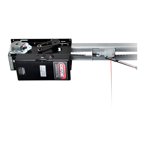
GCL-MT
Medium Duty Operator
For Z Series MODEL
OPGMZT5011B
APPLICATIONS:
Trolley (Drawbar) Operators can be assembled in the following configurations:
• Trolley (Drawbar)
Trolley Operators can be installed on the following types of doors:
• Sectional Doors (Standard Lift and Low Head Room Track)
HP/Max Door Weight/Height:
• 1/2 HP Only - 620lbs./14 ft.
This installation manual provides the information required to install,
program, troubleshoot and maintain a GCL-MT operator.
113089.00231
Trolley Operator
NOT FOR RESIDENTIAL USE
09/2021
Advertisement
Table of Contents

Related Manuals for Genie GCL-MT


Summary of Contents for Genie GCL-MT
- Page 1 Trolley Operators can be installed on the following types of doors: • Sectional Doors (Standard Lift and Low Head Room Track) HP/Max Door Weight/Height: • 1/2 HP Only - 620lbs./14 ft. NOT FOR RESIDENTIAL USE This installation manual provides the information required to install, program, troubleshoot and maintain a GCL-MT operator. 113089.00231 09/2021...
-
Page 2: Table Of Contents
INDEX SECTION 1: General Information & Instructions General Information & Instructions ........................1.1 Safety Information & Instructions ........................1.2-1.3 Critical Installation Information - General ......................1.4 Critical Installation Information - Entrapment Protection ................1.5 SECTION 2: Operator Installation Pre-Installation ................................2.1 Assembly ...................................2.2-2.4 Installation ................................2.5-2.9 Clutch Adjustment ..............................2.10 SECTION 3: Operator Wiring Wiring Safety Information ............................3.1 General Internal Wire Diagram ..........................3.2 Line Voltage ..................................3.3 Low Voltage ..................................3.4 Wall Controls ................................3.5-3.6 Accessory Overview ..............................3.7 Interlocks, Sectional Doors . -
Page 3: Section 1: General Information & Instructions
Section 1: General Information & Instructions Job Site Issues to Consider/Concerns The following list of items should be considered prior to selecting an operator for a given job site. 1. Available power supply. 2. Type of door. 3. Potential operator mounting obstructions. Items to consider include, but are not limited to: Room above door shaft, room below door shaft, available mounting surface integrity, power supply location, and convenient release cable positioning. 4. Size of door for appropriate operator torque and door travel speed selection. 5. Operator mounting environment. Items to consider include operator location, dampness of location, dustiness of the location and corrosiveness of the location. 6. Door activation needs/requirements. Examples include 3 button control stations, 1 button control stations, radio controls, pull cords, loop detectors, photoelectric controls, key switches, etc. See ENTRAPMENT PROTECTION Sec-1.5. 7. Interlock switches are required under certain conditions for doors with pass doors, door lock and dock levelers. 8. Accessory equipment. Examples include reversing edges and/or photocell beams, which are required for doors set to operate as momentary contact, auxiliary control relays, warning lights, etc. See ENTRAPMENT PROTECTION Sec-1.5. CAUTION Check working condition of door before installing the operator. Door must be free from sticking and binding. If equipped, deactivate any door locking device(s). Door repairs and adjustments, including cables and spring assemblies MUST be made by a trained service representative using proper tools and instructions. -
Page 4: Safety Information & Instructions
Section 1: Safety Information & Instructions WARNING Overhead doors are large, heavy objects that move with the help of springs under high tension and electric motors. Since moving objects, springs under tension, and electric motors can cause injury, your safety and the safety of others depend on you reading the information in this manual. If you have any questions or do not understand the information presented, call your nearest service representative. For the number of your local Genie Dealer, call 800-OK-GENIE. In this manual the words Danger, Warning, and Caution are used to stress important safety information. The word: DANGER indicates an imminently hazardous situation which, if not avoided, will result in death or serious injury. WARNING indicates a potentially hazardous situation which, if not avoided, could result in death or serious injury. CAUTION indicates potentially hazardous situation which, if not avoided, may result in injury or property damage. The word NOTE, is used to indicate important steps to be followed or important considerations. POTENTIAL HAZARD EFFECT PREVENTION DO NOT operate unless the doorway is in sight and free of obstructions. MOVING DOOR WARNING Keep people clear of opening while door is moving. - Page 5 Section 1: Safety Information & Instructions AVERTISSEMENT Les portes basculantes sont de gros objets lourds qui fonctionnent à l’aide de ressorts soumis à une haute tension et de moteurs électriques. Dans la mesure où les objets en mouvement, les ressorts sous tension et les moteurs électriques peuvent entraîner des blessures, votre sécurité et celle des autres exigent que vous preniez connaissance des informations stipulées dans ce manuel. Si vous avez des questions ou si vous ne comprenez pas les informations ci-incluses, veuillez contacter le représentant de service le plus près. Pour obtenir le numéro du revendeur Genie local, appelez le +1 (800) OK-GENIE. Dans ce manuel, les mots Danger, Avertissement, et Attention sont utilisés pour faire ressortir d’importantes informations relatives à la sécurité. Le mot : DANGER signale une situation dangereuse imminente qui si elle n’est pas évitée, risque d’entraîner des blessures graves, voire mortelles. AVERTISSEMENT signale une situation potentiellement dangereuse qui, si elle n’est pas évitée, risque d’entraîner la mort ou des blessures graves. ATTENTION signale une situation potentiellement dangereuse qui, si elle n’est pas évitée, risque d’entraîner des blessures ou des dommages matériels. Le terme REMARQUE est utilisé pour signaler les étapes importantes à suivre ou d’importants éléments à prendre en considération. DANGER POTENTIEL EFFET PRÉVENTION Utiliser uniquement si la porte est en vue et libre de tout obstacle. Ne PORTE EN MOUVEMENT AVERTISSEMENT laisser personne se tenir dans l’ouverture de la porte pendant qu’elle est en Pourrait entraîner des mouvement. blessures graves voire la Ne pas permettre aux enfants de jouer avec l’opérateur de la porte. mort Ne pas modifier la commande de l’opérateur à contact momentané à moins qu’un moyen d’inversion externe soit installé.
- Page 6 Section 1: Critical Installation Information IMPORTANT INSTALLATION INSTRUCTIONS WARNING To reduce the risk of severe injury or death: 1. READ AND FOLLOW ALL INSTALLATION INSTRUCTIONS. 2. Install only on a properly operating and balanced door. A door that is operating improperly could cause severe injury. Have qualified service personnel make repairs to cables, spring assemblies and other hardware before installing the operator. 3. Remove all pull ropes and remove, or make inoperative, all locks (unless mechanically and/or electronically interlocked to the operator) that are connected to the door before installing the operator. 4. Install the door operator at least 8feet. (2.44m) or more above the floor if operator has exposed moving parts. If the operator must be installed less than 8feet. (2.44m) above the floor, then exposed moving parts must be protected by covers or guarding, provided by the operator manufacturer. 5. Do not connect the door operator to the power source until instructed to do so. 6. Locate the control station: (a) within sight of the door, (b) a minimum of 5ft. above the floor so that small children cannot reach it, and (c) away from all moving parts of the door. 7. Install the Entrapment Warning Placard next to the control station and in a prominent location. 8. For products having a manual release, instruct the end user on the operation of the manual release. IMPORTANT INSTRUCTIONS D’INSTALLATION AVERTISSEMENT Pour réduire les risques de blessures graves ou de mort:...
- Page 7 Section 1: Critical Installation Information IMPORTANT INSTALLATION INFORMATION ENTRAPMENT PROTECTION: The installation of a monitored fail safe external reversing device is required on all momentary contact electronically operated commercial doors. If such a reversing device is not installed, the operator will revert to a constant contact control switch for close operation. The Reversing Devices currently UL Approved are: • MillerEdge® ME and MT series monitored edge sensors used in combination with Timer-Close Module (TCM) P/N OPABTCGX.S or Sensing Module (ESM) P/N OPABESX.S • MillerEdge® ME and MT series monitored edge sensors used in combination with MillerEdge Interface Module P/N OPAKMEIGX.S. (Direct connect through STB inputs.) • MillerEdge® Wireless (MEL) monitored edge sensor P/N OPAKGMMWE2.S. (Direct connect through STB inputs.) • ASO Sentir GF Series Monitored Sensing Edges used in combination with Timer Close Module (TCM) P/N OPABTCGX.S or Edge Sensing Module (ESM) P/N OPABESX.S • Residential Safe-T-Beam® Monitored Photocells - P/N 37220R (GST B-BX) and commercial P/N 38176R.S (includes extension brackets). • Series II Commercial Safe-T-Beam® Monitored Photocells - P/N OPAKPE2.S and OPAKPEN4GX.S (NEMA 4X). • Monitored Retro-Reflective Photocells - P/N OPGAKRPEN4X.S (NEMA 4X). • Monitored MillerEdge Light Curtain -P/N OPAKMLC3.S & OPAKMLC6.S Monitored Sensing Edges are available in any door width. NOTE: DO NOT use take up reels in conjunction with the Monitored Sensing Edge system. Use Coil Cords Only.
-
Page 8: Section 2: Operator Installation
Section 2: Operator Installation The drawbar operator consists of the: A. Operator B. Drawbar Track C. Chain Guides D. Drawbar Arm E. Front Spreader F. Front Idler Sprocket G. Drive Chain H. Drive Sprocket I. Carriage NOTE: Drawbar tracks must be 29 inches longer than the door’s height. Tracks have been sized properly and pre-punched for the chain guide assemblies from the factory. Sec-2.1... - Page 9 Section 2: Operator Installation 1. Attach Track to operator using two 7/16”-14 x 1” hex bolts, lock washers & hex nuts & two 1/4”-20 x 3/4” grade 8 bolts and lock nuts. FIG. 1. 1/4”-20x3/4” Grade 8 Bolt 7/16”-14x1” Bolt 1/4” -20 Lock Nut 7/16” Lock Washer 7/16” -14 Hex Nut FIG. 1 CAUTION Verify that screws are properly seated in track. Failure to seat screws can cause carriage to bind in door track. ATTENTION Vérifiez que les vis sont bien en place dans la piste. Si les vis sont mallogées, le chariot peut se coincer dans la piste de la porte. 2. Install chain guides. NOTE: Space chain guides evenly between operator and header. PLASTIC CHAIN GUIDE Add a chain guide for every 4 feet of door height per chart A. CHART A Under 12’...
- Page 10 Section 2: Operator Installation 3. Insert the carriage into the tracks as shown in FIG. 3. 4. Place the spreader bracket in position around the drawbar track. Do not insert the track bolts and lock nuts at this time. The spreader bracket will be held in place (temporarily) by the idler pin which holds the sprocket. 5. Install the idler sprocket inside the track by inserting the 7/16” x 7” idler pin through one side of the track. Feed pin through a sleeve and the idler sprocket followed by the second sleeve. Place 7/16” x 1-1/4” fender washer over each end of idler pin. Secure idler pin with cotter pin through the hole in each end of idler pin. FIG. 4. FIG. 3 IDLER SPROCKET WASHER & COTTER PIN THIS SIDE TRACK BOLTS/ LOCK NUTS DO NOT INSTALL YET! FRONT SPREADER BRACKET IDLER PIN SLEEVE COTTER PIN WASHER FIG.
- Page 11 Section 2: Operator Installation 1. Uncoil the drawbar chain and install by routing the chain over the chain guides (A) and around the drive sprocket (B) on the output shaft as shown in FIG. 5. 2. Attach to chain tension adjusting bolt (C) using a master link (provided). 3. Pass the other end of the chain between the header bracket and the idler sprocket (D). Make certain the chain is not twisted. 4. Attach the chain to the carriage using allen head bolt and nut (E). 5. Insert the adjusting bolt through the hole in the carriage and place the tensioning spring, flat washer and adjusting nut onto the bolt. DETAIL A, FIG. 5. 6. Tighten chain so that it will not jump the sprocket. Install and tighten lock nut. Check to ensure the following: • The chain is properly engaging the output sprocket. • The chain is not twisted. DETAIL A FIG. 5 Sec-2.4...
- Page 12 Section 2: Operator Installation CAUTION Check working condition of door before installing the operator. Door must be free from sticking and binding. If equipped, deactivate any door locking device(s). Door repairs and adjustments, including cables and spring assemblies MUST be made by a trained service representative using proper tools and instructions. If the door lock is to remain functional, an interlock switch MUST be installed which will prevent operation of the door whenever the door lock is engaged. Refer to the Wiring Instructions of this manual for proper connection of the interlock switch. ATTENTION Vérifiez l’état de fonctionnement de la porte avant d’installer l’opérateur. La porte doit pouvoir bouger librement et ne pas coincer. Désactivez tous les dispositifs de verrouillage de la porte (si équipés). Les réparations et les réglages de porte, plus particulièrement pour les câbles et les ressorts DOIVENT être effectués par un technicien qualifié qui se sert d’outils appropriés et qui respecte les instructions. Si le verrouillage de la porte doit rester fonctionnel, un commutateur de verrouillage DOIT être installé pour empêcher le fonctionnement de la porte chaque fois que le verrouillage de la porte est engagé. Reportezvous aux instructions de câblage de ce manuel pour établir une connexion correcte de l’interrupteur de verrouillage. WARNING Repairs and adjustments, including particularly to cables and spring assemblies under high tension, must be made by a trained service representative using proper tools and instructions. AVERTISSEMENT Les réparations et les réglages, plus particulièrement aux câbles et ensembles de ressort sous tension élevée doivent être effectués par un professionnel qui se sert d’outils appropriés et qui respecte les instructions. Sec-2.5...
- Page 13 Section 2: Operator Installation 1. Measure the width of the door to determine the center. Make a vertical line above the door, as shown in FIG. 6. • If the vertical line is not in line with a door stile, a means of attaching the door bracket to the door must be provided. This can be accomplished by spanning the center of the door’s top section (between the top and bottom rail) with a suitable material such as wood or steel. 2. Prepare for attaching drawbar to header. If woodwork, or other suitable material is not already in place, securely affix a 2” x 6” block of wood or metal plate as shown in FIG. 6. 3. Center the block/plate on the header. 4. Mark the door’s vertical center line on this block/plate. ATTACHMENT MATERIAL VERTICAL LINE (SEE STEP 2) (SEE STEP 1) HORIZONTAL LINE (SEE STEP 6) HEADER CENTERLINE OF DOOR FIG. 6 Sec-2.6...
- Page 14 Section 2: Operator Installation 5. Use a level, as shown in FIG. 7, to find the highest point of travel for the door. 6. Mark a horizontal line across the vertical line you made on the header at 5” above the highest point of door travel. 7. Raise the door end of the drawbar while resting the operator on the floor or other suitable material. 8. Position the spreader bracket on the centerline with its bottom edge on the horizontal mark. FIG. 8. 9. Fasten spreader bracket to header using fasteners appropriate for the header material. MARK A HORIZONTAL LINE 5” ABOVE HIGHEST POINT OF TRAVEL 2" x 6" LEVEL HEADER HIGHEST POINT OF TRAVEL FIG. 7 FIG. 8 Sec-2.7...
-
Page 15: Assembly
Section 2: Operator Installation 1. Raise the operator and position it so that the drawbar tracks are level and perpendicular to the face of the door (or the stile where the door bracket will be attached). FIG. 9. 2. Lock the drawbar tracks into the spreader bracket using two 1 /4”-20 x 9/16” track bolts & two lock nuts. NOTE: Track bolts MUST be installed from inside the track. 3. Secure the operator in position by installing steel angles (not provided) between the ceiling superstructure and the operator. FIG. 10. ROPE, CABLE, TRACK BOLTS CHAIN, ETC. & LOCK NUTS LEVEL INSTALL CARRIAGE BOLTS UNDER PLATE DOOR FROM ABOVE WALL WALL FIG. - Page 16 Section 2: Operator Installation 1. Pull down on the drawbar arm locking sleeve and attach to carriage. (See NOTE 4) 2. Position the door bracket on the door as shown in FIG. 11, with mounting holes on the door centerline. (Even with or above top door roller). NOTE 1: Use a reinforcement bracket. Do not attach door bracket directly to door section. 3. For wood doors, fasten the door bracket to the door using two 1/4”-20 x 2-1/4” carriage bolts and nuts. For metal doors, use two 1/4”-20 self-tapping sheet metal screws, or as recommended by the door manufacturer. 4. Use two 3/8”-16 x 7/8” bolts and nuts to attach the door arms together. NOTE 2: Use the set of holes that align the drawbar arms at a 20-30 degree rearward angle. FIG. 12. NOTE 3: If the door strut interferes with the mounting of the door bracket, position the door bracket below the strut.
-
Page 17: Clutch Adjustment
Section 2: Operator Installation Clutch Adjustment The GCL-MT operators have a friction-style clutch that can be adjusted. NOTE: The clutch is intended to provide protection for the door, CLUTCH PULLEY the operator and associated equipment. It is not intended for entrapment protection. Therefore, the adjustment of the clutch WASHER CLUTCH PAD should be such that the door and operator function in this manner. -
Page 18: Section 3: Operator Wiring
Section 3: Wiring WARNING • DO NOT apply power to operator until instructed to do so. • It is strongly recommended, and may be required by law in some areas, that line voltage wiring be performed by a qualified electrician. • Be sure that electrical power has been disconnected from the input power wires being connected to the operator prior to handling these wires. An appropriate lock-out/tag-out procedure is recommended. • Line voltage wiring must meet all local building codes. • Make sure operator voltage, phase and frequency nameplate ratings are identical to the job site line voltage ratings. • Input power wiring must be properly sized for the operators amperage rating located on the nameplate. • To reduce the risk of electric shock, make sure the chassis of this unit is properly grounded. AVERTISSEMENT • NE PAS mettre sous tension tant que l’instruction n’est pas donnée de le faire. • Il est fortement recommandé voire même exigé par la loi dans certaines régions, de contacter un électricien qualifié pour l’acheminement du fil électrique. • Assurez-vous que l’alimentation électrique a été déconnectée des câbles d’alimentation d’entrée connectés à l’opérateur avant de manipuler ces câbles. Une procédure de verrouillage/étiquetage appropriée est recommandée. • Le câblage au secteur doit satisfaire à tous les codes de construction locaux. • Assurez-vous que les valeurs nominales de la plaque signalétique pour tension, phase et fréquence de l’opérateur correspondent à celles des tensions de l’alimentation sur site. • La capacité d’entrée doit correspondre à la valeur nominale de l’ampérage des opérateurs indiquée sur la plaque signalétique. • Pour réduire le risque de choc électrique, assurez-vous que le châssis de l’unité est correctement mis à la terre. - Page 19 Section 3: Wiring Sec-3.2...
-
Page 20: Line Voltage
Section 3: Wiring Line Voltage Wiring 1. Remove line voltage input plug and install proper fittings and 1/2” conduit. 2. Route proper line voltage wires into operator. 3. Locate line input terminals on circuit board. Using correct connectors, attach wires to line inputs, and ground terminal. • Keep low voltage and line voltage wires separate. • Route all line voltage wires as shown. • Plug all unused conduit holes. LINE INPUT TERMINALS HIGH VOLTAGE INPUT PLUG ROUTE LINE VOLTAGE WIRING IN SHADED AREA AS SHOWN LINE LINE IN GROUND POWER CONNECTIONS LINE NEUTRAL 120V... -
Page 21: Low Voltage
Section 3: Wiring Low Voltage Control Wiring 1. Connect all low voltage control circuit wires using 1/2” conduit or flexible convoluted tubing. • Keep low voltage and line voltage wires separate. • Route all low voltage control wiring as shown. This includes all control circuit wires such as wall controls, interlock switches and single button input devices as well as safety circuit wiring. • Plug all unused conduit holes. LOW VOLTAGE CONTROL WIRE TERMINAL STRIP LOW VOLTAGE INPUT PLUG ROUTE LOW VOLTAGE WIRE IN SHADED AREA Sec-3.4... -
Page 22: Wall Controls
Section 3: Wiring Wall Controls WARNING • Wall Control(s) must be located so that the door is within sight of the user and is far enough from the door, or positioned such that the user is prevented from coming in contact with the door while operating controls. • Attach the Warning placard adjacent to the Wall Control. FIG. 4. AVERTISSEMENT • La ou les commandes murales doivent être situées de telle sorte que l’utilisateur puisse voir la porte et positionnées de telle sorte que l’utilisateur ne puisse pas entrer en contact avec la porte lorsqu’il se sert des commandes. • Fixez le poster d’avertissement à côté de la commande murale. FIG. 4 WARNING Before momentary contact control can be used on the CLOSE button, a monitored external reversing device such as a photocell system or sensing edge switch must be used. See ENTRAPMENT SECTION for installation of entrapment protection devices. AVERTISSEMENT Avant d’utiliser la commande à contact momentané sur le bouton FERMETURE, un dispositif d’inversion externe surveillée tel qu’un système de cellule photoélectrique ou un commutateur de détection de bord doit être utilisé. Voir l’installation des dispositifs de protection contre le coincement en. Sec-3.5... - Page 23 Section 3: Wiring 1. For a single open/close/stop installation, make connections as shown in FIG. 1. 2. For single button accessory controls, make connections as shown in FIG. 2. 3. For a multiple open/close/stop installations, make connections as shown in FIG. 3. 4. Install WARNING placard next to control station. FIG. 4 CONTROL SIGNAL TERMINAL STRIP CONTROL SIGNAL TERMINAL STRIP 3-BTN STOP 1-BTN OPEN CLOSE STOP Station OPEN CLOSE 1-BTN STOP NOTE: Station JUMPER BETWEEN STOP AND GND TERMINALS MUST BE REMOVED Switch Station FIG.
- Page 24 Exclusive use of Non-Monitored devices will prevent the use of momentary contact to close operation. Sensing Edges, Wireless See ENTRAPMENT PROTECTION Sec-1.5 for a list of approved monitored safety edge devices. See instructions included with the sensing edge for detailed installation and programming instructions. Wire directly to the control board at the ODC STB terminals. NOTE: The ODC STB must be programmed to ON on the control board. See programming section in this manual for details. Accessory Modules The GCL-MT operators can accommodate, up to, two accessory module boards for expanded features. See instructions included with the Accessory Module(s) for detailed features, installation and programming instructions. Sec-3.7...
- Page 25 Section 3: Wiring Interlock Switches Optional external interlock switches are required with some doors to prevent the door from operating under certain conditions including the following: • If the door is equipped with a functioning door lock, an interlock switch (A) must be installed to prevent electric operation when the lock is engaged. • If the door is equipped with a pedestrian pass-through door, an interlock switch (B) must be installed at the pass-through door in order to prevent electrical operation when the pass-through door is open. • If the door is equipped with a dock leveler the interlock circuit may be connected to the dock leveler to prevent motor operation when the leveler is not in the down position. CONTROL SIGNAL TERMINAL STRIP NOTE: If external interlock is used, the jumper wire between the EXT INTLK terminals MUST be removed. INTLK INTLK * REMOVE SWITCH JUMPER 075412-0000...
-
Page 26: Photocells
Section 3: Wiring Photocells WARNING Actuating the operator by using constant contact on the CLOSE button will override non-functioning external reversing devices, including photocells. AVERTISSEMENT L’activation de l’operateur en util isant un contact constant sur le bouton FERMER annulera les dispositifs d’inversions externes, y compris les cellules photoelectriques. WARNING Photocell systems provide entrapment protection when mounted near the doorway in such a way that the lower portion of an individual’s leg will break the photocell beam during normal walking conditions. AVERTISSEMENT Les systèmes de cellules photoélectriques fournissent une protection contre le coincement pour le montage à proximité de la porte de manière à ce que la partie inférieure de la jambe d’un individu ne puisse pas rompre le faisceau de la cellule photoélectrique lors de passages normaux par la porte. MONITORED PHOTOCELLS: Monitored (STB) photocells FIG. 5. Wiring to these photocells can be connected to either terminal (they are not polarity sensitive). See ENTRAPMENT PROTECTION Sec-1.5 for approved reversing devices. NOTE: Installer must enable ODC STB in CALIBRATION MODE. (See programming section) NON-MONITORED PHOTOCELLS: Nominal 24 Volt DC commercial photocells with normally open contacts can be connected as shown. FIG. 6. NOTE: External radio connector harness supplies 20-40VDC across blue(+) and yellow(-) wires. NOTE: If no voltage is present across blue &... - Page 27 Section 3: Wiring Photocells CONNECT WIRES TO EITHER TERMINAL. Monitored Type Photocells (NOT POLARITY SENSITIVE) CONTROL SIGNAL TERMINAL STRIP RESIDENTIAL SAFE-T-BEAM® (STB) 20-40 VDC @ 250mA MAX. CURRENT FIG. 5 EXT RADIO CONNECTOR CONTROL SIGNAL TERMINAL STRIP SAFETY SAFETY Non-Monitored Type Photocells RELAY + 24VDC RADIO...
- Page 28 Section 3: Wiring Monitored Edges, Hardwired WARNING Actuating the operator by using constant contact on the CLOSE button will override non-functioning external reversing devices, including sensing edges. AVERTISSEMENT L’activation de l’operateur en util isant un contact constant sur le bouton FERMER annulera les dispositifs d’inversions externes, y compris les systèmes de détection des bords. MillerEdge® “DC” Series & ASO Monitored Sensing Edge Installation with Interface Module. Right-hand installation shown, Left-hand installation mirrored 1. Mount junction box to wall one half the door height plus 12 inches from floor. 2. Install hard-wiring from operator and coil cord to junction box and secure with conduit clamps. 3. Connect hard-wiring from operator to coil cord with wire nuts and install junction box cover plate. These are not polarity sensitive. 4. Install wires to ODC STB terminals in operator. 5. Attach coil cord to Monitored Edge Interface Module in junction box as shown and secure with conduit clamps.
- Page 29 Section 3: Wiring Monitored Edges, Wireless WARNING Actuating the operator by using constant contact on the CLOSE button will override non-functioning external reversing devices, including sensing edges. AVERTISSEMENT L’activation de l’operateur en util isant un contact constant sur le bouton FERMER annulera les dispositifs d’inversions externes, y compris les systèmes de détection des bords. MillerEdge® Wireless Monitored Sensing Edge Installation Right-hand installation shown, Left-hand installation mirrored 1. Mount Wireless Edge Receiver adjacent to operator. 2. Route MEL wireless receiver wires into operator electric box using suitable conduit and clamp systems. 3. Attach MEL wireless receiver power wires (blue/yellow) to external radio plug as shown below. 4. Attach MEL wireless receiver trip wires (white/white) to ODC STB terminals on control wire terminal strip. 5. Mount MEL wireless transmitter to bottom edge of door per MEL instructions. NOTE: Installer must enable ODC STB in CALIBRATION MODE (see programming section) OPERATOR TERMINAL MEL-II...
-
Page 30: Sensing Edge, Hardwire With Expansion Board
Section 3: Wiring Sensing Edges, Hardwired with Expansion Board WARNING Actuating the operator by using constant contact on the CLOSE button will override non-functioning external reversing devices, including sensing edges. AVERTISSEMENT L’activation de l’operateur en util isant un contact constant sur le bouton FERMER annulera les dispositifs d’inversions externes, y compris les systèmes de détection des bords. Miller Edge ‘DC’ Series & ASO Sentir GF Series Monitored Sensing Edge Installation with Timer Control Module (TCM) or Edge Sensing Module (ESM) 1. Mount junction box to wall one half the door height plus 12 inches from floor. 2. Install hard-wiring from operator and coil cord to junction box and secure with conduit clamps. -
Page 31: Non-Monitored Safety Edge
Section 3: Wiring Non-Monitored Safety Edge WARNING Actuating the operator by using constant contact on the CLOSE button will override non-functioning external reversing devices, including sensing edges. AVERTISSEMENT L’activation de l’operateur en util isant un contact constant sur le bouton FERMER annulera les dispositifs d’inversions externes, y compris les systèmes de détection des bords. 1. Route wires into operator electric box using suitable conduit and clamp systems. 2. Attach wires to N-O SAFETY terminals on control wire terminal strip. CONTROL SIGNAL TERMINAL STRIP SAFETY SAFETY Non-Monitored Safety Edge External Radio Installation (Optional) Installing external radio for remote operation. FIG. 8 1. Make wire connections to external radio harness (provided) as shown. 2. Install harness to external radio harness plug on control board as shown. NOTE: A monitored safety device must be used when installing an external radio for remote operation. - Page 32 Section 4: Programming Apply Power To Operator DANGER After power is supplied to the operator, DO NOT make contact with components inside the control panel except for the Keypad Keys. DANGER Après avoir mis l’opérateur sous tension, NE PAS entrer en contact avec des composants à l’intérieur du panneau de commande, sauf pour les touches du pavé numérique. WARNING DO NOT calibrate operator or operate door unless doorway is in sight and free of obstructions. Door will move during setup. Keep people clear of opening while door is moving. AVERTISSEMENT Calibrer l’opérateur et utiliser la porte uniquement si la porte est en vue et libre de tout obstacle. La porte se déplacera pendant la programmation. Ne laisser personne se tenir dans l’ouverture de la porte pendant qu’elle est en mouvement CAUTION This door is operated by a limited-duty operator. To prevent the motor protector from tripping, do not exceed 15 cycles of opening and closing per hour. NOT FOR RESIDENTIAL USE ATTENTION Cette porte est actionnée par un opérateur de service limité. Pour éviter que la protection du moteur ne se déclenche pas, ne pas dépasser 15 cycles d’ouverture et de fermeture à l’heure. NON DESTINÉ POUR USAGE RÉSIDENTIEL. Sec-4.1...
- Page 33 Section 4: Programming Calibration Mode Structure If at any time should programming become confused. Press the CAL/RUN key once to enter RUN MODE then press CAL/RUN key again to re-enter CALIBRATION MODE. Press the SCROLL key(s) to locate or check the settings on any menu item. Operator Calibration Menu Structure 1. Open Mode 2. Close Mode...
-
Page 34: Close Direction
Section 4: Programming Setting Close Direction The direction of motor rotation depends on mounting position and/or how the main input power phases are wired. This setting is used to ensure the door is closing and opening according to the input commands. NOTE: Make sure door is in mid-travel. -
Page 35: Travel Limits
Section 4: Programming Setting Travel Limits 1. If operator is in RUN mode, press CAL/RUN key to enter CALIBRATION MODE. 2. Use the SCROLL Key to scroll through the menu until UP LIMIT > CLR is displayed. 3. Jog the door using the OPEN key until you reach the desired height. 4. Press SET/CLEAR key to switch display to UP LIMIT>SET . FIG. 5. 5. Press SCROLL DN key until display reads DOWN LIMIT CLR. 6. Jog door down to 2in. from floor. (See note below). 7. Press SET/CLR to switch display to DOWN LIMIT SET. FIG. 6. 8. Press SCROLL DN key until display reads LIMIT OVERRUN. OPEN OPEN UP LIMIT DOWN LIMIT SET CLOSE CLOSE STOP STOP SCROLL SCROLL CLEAR CLEAR SCROLL SCROLL FIG. 6 FIG. -
Page 36: Blank
THIS PAGE INTENTIONALLY BLANK Sec-4.5... -
Page 37: Limit Overrun
Section 4: Programming Setting Limit Overrun WARNING The Limit Overrun will override external reversing devices, including photocells and sensing edges or reversing edges. Therefore, any externally connected devices will be disabled during that portion of the door travel controlled by the Limit Overrun function. The Down Limit Overrun function should be used to close the door no more than the final 2in. AVERTISSEMENT La fonction de dépassement de limite annulera les dispositifs de renversement externes, y compris les cellules photoélectriques et des systèmes de détection ou d’inversion aux bords. En conséquence, tous les dispositifs externes connectés seront désactivés pendant la partie de la course de la porte qui est contrôlée par la fonction de dépassement de limite. La fonction de dépassement de limite inférieure doit être utilisée pour fermer la porte uniquement aux derniers 5 cm. A. The Limit Overrun setting is a matter of trial and error. The goal is to adjust the Limit Overrun until an appropriate seal is obtained between the bottom edge of the door and the floor. B. The Limit Overrun setting can be varied between 0 and 9. 0 - disables the Limit Overrun so that the door stops at the down limit switch setting. 9 - causes the greatest amount of door travel beyond the limit switch setting. Door should close gently with light tension on door cables, or minimal stacking on rolling steel slats. 1. If operator is in RUN mode, press CAL/RUN key to enter CALIBRATION MODE. 2. Use the SCROLL key to scroll through the menu until LIMIT OVERRUN is displayed. 3. Press SET/CLEAR until the display reads the desired value (1-9). FIG. 8. OPEN 4. Press the OPEN key to open the door a few feet, then release. LIMIT OVERRUN # CLOSE 5. Press the CLOSE key to close the door and hold until the operator stops. -
Page 38: Monitored Reversing Devices
Section 4: Programming Monitored Reversing Devices WARNING Photocell systems provide entrapment protection when mounted near the doorway in such a way that the lower portion of an individual’s leg will break the photocell beam during normal walking through the doorway. AVERTISSEMENT Les systèmes de cellules photoélectriques fournissent une protection contre le coincement s’ils sont installés à proximité de la porte de manière à ce que la partie inférieure de la jambe d’un individu puisse rompre le faisceau de la cellule photoélectrique lors de passages normaux par la porte. 1. If operator is in RUN mode, press CAL/RUN key to enter CALIBRATION MODE. 2. Use the SCROLL Key to scroll through the menu until ODC STB>OFF is displayed. Press SET/CLEAR key to toggle to ODC STB > ON. FIG. 9. 3. Press CAL/RUN to return to run mode, or continue with setting OPEN AND CLOSE MODE programming on the next page. NOTE: See ENTRAPMENT PROTECTION Sec-1.5 for approved monitored reversing devices. See Sec- 3 for wiring of approved monitored sensing devices that can be installed onto the ODC STB operator terminals. NOTE: Turn this feature ON if monitored reversing device is connected to the operators ODC STB terminals. - Page 39 Section 4: Programming Setting Open and Close Modes (Constant vs. Momentary Contact) WARNING Before momentary contact control can be used on the CLOSE button, a monitored external reversing device such as a photocell system or sensing edge switch must be used. See WIRING SECTION for installation of entrapment protection devices. AVERTISSEMENT Avant d’utiliser la commande à contact momentané sur le bouton FERMETURE, un dispositif d’inversion externe surveillée tel qu’un système de cellule photoélectrique ou un commutateur de détection de bord doit être utilisé. Voir la section CÂBLAGE pour l’installation des dispositifs de protection contre les piégeages. OPEN 1. If operator is in RUN mode, press CAL/RUN to enter CALIBRATION MODE. 2. Press SCROLL key until display reads OPEN MODE>MOM or OPEN MODE>C-STP. • MOM=momentary contact, meaning you press and release the OPEN or pushbutton and the door will continue to move until it reaches its travel limit. (See NOTE). • C-STP=constant contact-stop, meaning if you release the OPEN key or pushbutton prior to the door reaching its travel limit, the door will stop. 3. Press SET/CLEAR key to toggle between OPEN MODE>C-STP or OPEN MODE>MOM on the display. 4. Press CAL/RUN to return to run mode, or continue to CLOSE MODE programming below. CLOSE 5. If operator is in RUN mode, press CAL/RUN to enter CALIBRATION MODE. 6. Press SCROLL down arrow key until display reads CLOSE MODE>MOM, CLOSE MODE>C-STP or CLOSE MODE>C-REV.
-
Page 40: Transmitter Programming
Section 4: Programming Transmitter Programming (Optional) Adding a Transmitter 1. If operator is in RUN mode, press CAL/RUN to enter CALIBRATION MODE. 2. Press SCROLL (up or down) until display reads LEARN NEW XMTR? FIG. 1. • This question along with the instruction HIT SET FOR YES will continuously pan across the display window. (Pressing SCROLL or CAL/RUN will cancel the operation). 3. Press SET/CLEAR. • Display will read PUSH XMTR BUTTON TWO TIMES TO LEARN XMTR. 4. Press transmitter button two times. • The display will read XMTR ___LEARNED. Where it assigns a random number to the transmitter. That transmitter is entered and ready to operate the door. (Label/mark the transmitter). 5. Press SCROLL (up or down) to move on to another menu item, or CAL/RUN to exit CALIBRATION mode. Removing Individual Transmitter 6. If operator is in RUN mode, press CAL/RUN to enter CALIBRATION MODE. 7. Press SCROLL (up or down) until display reads CLR ONE XMTR? FIG. 2. 8. Press SET/CLEAR. • A menu displaying the available transmitter numbers will appear. • Press SCROLL (up or down) to cycle through the menu to the number of the transmitter to be removed. (Pressing CAL/RUN will cancel the operation). -
Page 41: Mid-Stop
Section 4: Programming Mid-Stop Limit (Optional) NOTE: Setting of the MID-STOP should only be performed AFTER the travel limits and max run timer settings have been made. 1. If operator is in RUN mode, press CAL/RUN to enter CALIBRATION MODE. 2. Press the CLOSE key to close the door to the down limit. 3. Press SCROLL (up or down) until display reads MID-STOP > CLR. FIG.4 • If display reads MID-STOP > SET, Press the SET/CLEAR key to reset to CLR. 4. Press the OPEN key to open door to desired height. 5. Press SET/CLEAR key to set mid-stop. Display will show MID-STOP > SET. 6. Press CAL/RUN key to return to RUN mode. -
Page 42: Max Run Timer
Section 4: Programming Resetting the Max Run Timer (MRT) CAUTION The MID-STOP feature must be turned off in order to properly set the Max Run Timer. ATTENTION La fonction MID-STOP doit être désactivée afin de régler correctement la minuterie de course maximum. NOTE: The Max Run Timer is set automatically once the unit is cycled between limits. NOTE: The Max Run Timer prevents the unit from running continuously in the event of a problem. The MRT is set to the time required to run from one limit to the other, plus 5 seconds (nominal). - Page 43 Section 4: Programming Operator Cycle Count 1. Press CAL/RUN to enter CALIBRATION MODE. 2. Press SCROLL until display reads CYCLES>1,2,3 etc. where the number shown is the number of open/ close cycles the operator has performed. FIG. 7. 3. Press CAL/RUN to return to RUN mode. OPEN CYCLES CLOSE STOP SCROLL CLEAR SCROLL FIG. 7 Sec-4.12...
-
Page 44: Gdo Type
Section 4: Programming GDO and Display Firmware 1. Press CAL/RUN to enter CALIBRATION MODE. 2. Press SCROLL until display reads GDO V# > #####. FIG. 8. • This display will cycle between the version number of the current GDO firmware and the current display firmware. 3. Press CAL/RUN to return to RUN mode. OPEN OPEN DISPLAY V# #### GDO V# ###### CLOSE CLOSE STOP STOP SCROLL CLEAR SCROLL CLEAR SCROLL SCROLL FIG. 8 GDO Type This operator is available for use in trolley configuration only. However, the same control board is used for jackshaft and trolley models. Service replacement boards need to have GDO TYPE set for the appropriate model configuration. -
Page 45: Section 5: Troubleshooting
Section 5: Troubleshooting The GCL-MT operators include a self-diagnostic circuit board using troubleshooting LED indicators to signal the technician of a problem. TROUBLESHOOTING LEDs ENAB + 24 ENAB '< ./& ./& 000-C.0 000-C.0 00"2, 00"2, .1"- &'.5" 5,.1 <B$,- + 24 5)8",9 5)8",9 +-,'( +-,'( INTLK HOIST INTLK INTLK HOIST INTLK DETAIL TROUBLESHOOTING LED’s HOIST EXTERNAL +24VDC... - Page 46 Section 5: Troubleshooting Display Operation in RUN Mode This operator will display its status on the integrated display. Each time the operator runs, stops, reverses or refuses to run, the display will indicate the operating action, what device initiated the action, and any error condition that prevented/impacted the intended operation. Once an error code has been generated, the operator will continue to display the error code while the operator is not running. This error code can be cleared by pressing the stop button or stop key on the keypad. The error code will automatically clear when the operator stops at the down limit. The last ten error codes will continue to be stored in the operator’s error code memory after they have been cleared from the display in the run mode. The operator will display any uncleared trouble codes, in turn, on the integrated display, alternating with the active condition (error or run) code, until all of the trouble codes have been cleared. Trouble codes can only be cleared after the condition causing the code has been resolved. Trouble codes are not cleared by pressing the stop button or stop key on the keypad. Trouble codes are stored in the operator’s memory. Run Codes To aid in troubleshooting problems, this operator includes a run code memory that stores the most recent ten events. These codes are stored with or without power. Each time the operator runs or stops, it generates a code that it stores in this memory, used together with the error code memory, it becomes a powerful troubleshooting aid. The run code memory stores the last ten codes in sequence. Once ten codes are stored, the oldest code is erased to make room for the newest code. These codes are displayed in calibration mode. The display will flash the number of the run code and the 2-digit code followed by a description of the run code. OPEN RUN CODE 1>xx CLOSE Clear code in run STOP mode SCROLL CLEAR SCROLL OPEN IN CALIBRATION MODE: RUN CODE 1>xx...
- Page 47 Section 5: Troubleshooting RUN CODES Code Display Detailed/Expanded Description Corrective Action IDLE > DOWN LIMIT The door is at the Down Limit position. None IDLE > UP LIMIT The door is at the Up Limit position. None IDLE > MID STOP The door is at the Mid-Stop Limit position. None IDLE > NO LIMIT The door is at no established limit position. None OPENING > OPEN The Open Pushbutton input was activated causing the door to move in the None opening direction. OPENING > ONE BTN The 1- Button input was activated causing the door to move in the open None direction. OPENING > RADIO The External Radio input was activated causing the door to move in the open None direction. OPENING > AUX The Auxiliary Open input (on the TCM Module) was activated causing the None OPEN door to move in the open direction. OPENING > OPEN The Open Key (on the circuit board) was activated causing the door to move None...
-
Page 48: Error Codes
Section 5: Troubleshooting Error Codes To aid in troubleshooting problems, this operator includes an error code memory that stores the most recent 10 error events. These codes are stored with or without power. The latest error code detected is also displayed on the lcd until the stop button or key is pressed or the operator stops at the down limit. The error code memory stores its codes in time sequence. Once 10 codes are stored, the oldest code will be erased to make room for the next newest code. These codes are displayed in calibration mode. The display will flash the number of the code in the sequence and the 2 digit code id, followed by a description of the code. -Scrolling Text- OPEN MODE CALIBRATION CLOSE STOP SCROLL CLEAR SCROLL Advance -Scrolling Text- OPEN ERROR CODE 1>xx XX>ERROR DECRIP. CLOSE STOP SCROLL CLEAR Cycle SCROLL Code Display Detailed/Expanded Description Corrective Action HALT > MODULE The door stopped because it determined there was a problem... - Page 49 Section 5: Troubleshooting Code Display Detailed/Expanded Description Corrective Action REV > MAX RUN TMR The door stopped traveling down and reversed because the Check the door balance. Check the Clutch adjustment to Maximum Run Time between Limits was exceeded. make sure it's not slipping. Re-record the Max Run Timer values in both directions. REV > EXP MOD FAIL The door stopped traveling down because it determined there Review the menu looking for a missing menu item. For was a problem with an Expansion Module. example, if the limit module is defective there will not be any limit setting information in the menu. STOP > HOT MOTOR The door stopped moving because the motor overheated. Check for a hot motor. Check the motor plug on the main board making sure the plug and wires are seated. STOP > OPEN MRT The door stopped traveling open because the Maximum Run Check the door balance. Check the Clutch adjustment to Time between Limits was exceeded. make sure it's not slipping. Re-record the Max Run Timer values in both directions. STOP > CLOSE MRT The door stopped traveling close because the Maximum Run Check the door balance. Check the Clutch adjustment to Time between Limits was exceeded. make sure it's not slipping. Re-record the Max Run Timer values in both directions. STOP > OPEN INTLK The door stopped because the Hoist Interlock or the External Check the Hoist Interlock switch and wires. Check an Interlock circuit became active (open).
- Page 50 Section 5: Troubleshooting Code Display Detailed/Expanded Description Corrective Action CHECK N-C SAFETY The unit will not close because it determined the Normally Check the Normally Close (N-C Safe) Input device wired Closed Reverse input on the Timer Close Module is active into the Timer Close Module and device wires for an open (Open circuit). circuit. CHECK MON. EDGE The unit will not close because it determined the Monitored Check the Monitored Edge (MON EDGE) Input device Edge (MON EDGE) input on the Timer Close Module is active. wired into the Timer Close Module and device wires. OVERHEATED The unit will not run because it determined the Thermal Check the door balance. Check the wires in the motor MOTOR Overload in the motor is active. connector that plugs into the circuit board. Replace the motor. NO RUN > DOWN The unit will not run because the Down/close input was User input error activated but the unit was already at the Down Limit position. NO RUN > UP LIMIT The unit will not run because the Up/open input was activated User input error but the unit was already at the Up Limit position. NO RUN > MID STOP The unit will not run because the Up/open input was activated User input error but the unit was already at or beyond the Mid Stop Limit position. This active input is preventing the unit from closing as well.
- Page 51 Section 5: Troubleshooting Code Display Detailed/Expanded Description Corrective Action LIMIT MOD. FAIL The unit has determined that the Limit Module has stopped Check the limit cable connection. Power the unit down communicating. and back up. If the error persist then replace the Limit Module. OPEN BTN BAD > PU The unit determined that the Open Pushbutton input was Check the Open Pushbutton and Open Pushbutton wires active (shorted) when power was applied. This input will be for a closed circuit. ignored until it changes state. CLOSE BTN BAD The unit determined that the Close Pushbutton input was Check the Closed Pushbutton and Close Pushbutton wires > PU active (shorted) when power was applied. This input will be for a closed circuit. ignored until it changes state. ONE BTN BAD > PU The unit determined that the 1- Button input was active Check the 1-Button and 1-Button wires for a closed circuit. (shorted) when power was applied. This input will be ignored until it changes state. RADIO BAD > PWR The unit determined that the External Radio input was active Check the External Radio for a short circuit. when power was applied. This input will be ignored until it changes state. AUX OPEN BAD > PU The unit determined that the Auxiliary Open input on the Check the Auxiliary Input device wired into the Timer Timer Close Module was active (shorted) when power was Close Module and Auxiliary Input device wires for a closed...
-
Page 52: Section 6: Service & Maintenance
Section 6: Service & Maintenance The following table provides a schedule of recommended service and maintenance items to be completed by qualified service personnel. CAUTION Failure to perform the recommended Service & Maintenance may result in premature failure of the operator. ATTENTION Si les instructions de service et de maintenance recommandés ne sont pas suivies, l’opérateur pourrait tomber en panne prématurément. WARNING To avoid SERIOUS INJURY or DEATH: • Disconnect power BEFORE performing ANY adjustment or maintenance. • ALL maintenance MUST be performed by qualified service personnel. AVERTISSEMENT Pour éviter LES BLESSURES GRAVES OU MORTELLES : • Coupez l’alimentation avant d’effectuer toute opération de réglage ou d’entretien. • Les opérations d’entretien doivent obligatoirement être effectuées par un personnel qualifié. Maintenance Schedule SERVICE ITEM SERVICE INTERVAL MONTHLY EVERY 3 MO. EVERY 6 MO. 5000 CYCLES 5000 CYCLES SENSING EDGE OPERATION CHECK BRAKE SYSTEM SPROCKET SET SCREWS MANUAL OPERATION SERVICE ITEM SERVICE INTERVAL EVERY 12 MO. - Page 53 Section 6: Service & Maintenance ELECTRIC BOX BILL OF MATERIAL PART NO. DESCRIPTION ITEM NO. 113125.0001 KIT, ENCLOSURE, MZ 111010.0001 BELT, POLY-V, STRETCH 111421.0003 LIMIT MODULE, X-SERIES, AK 110877.0046 CHAIN, #35 X 46P, LOOP 113068.0001 BRAKE ASSY, TROLLEY/JACKSHAFT, MZ 113057.0001 SHAFT ASSY, CLUTCH, TROLLEY, MZ 113058.0001 SHAFT ASSY, OUTPUT, TROLLEY...
- Page 54 Section 6: Service & Maintenance 2.0 AMP (FUSE WITH GREEN DOT) .315 AMP (FUSE WITH YELLOW DOT) BILL OF MATERIAL PART NO. DESCRIPTION ITEM NO. 113033.0001 BOX, ELECTRIC, MZ 110846.0001 XFMR, 120V 110950.0001 HINGE, ELECTRIC BOX 19988A CAPACITOR,70 MFD 111851.0002 COVER, ELECTRIC BOX, BLACK 111397.0001 RCVR ASSY, 315/390,...
- Page 55 Section 6: Service & Maintenance 113057.0001.S SHAFT ASSY, CLUTCH, TROLLEY, MZ 113058.0001.S SHAFT ASSY, OUTPUT, TROLLEY, MZ 113057.0001.S SHAFT ASSY, CLUTCH, TROLLEY, MZ PART NO. DESCRIPTION ITEM 113059.0001 SHAFT, CLUTCH, TROLLEY 110465.0001 SPROCKET, 11T, #35 CHAIN, 3/8 P 110313.0008 PIN, SPRING, .188 DIA DIA X 1.38 080415.0021 RING, RTNG, EXT, STL, 5/8"SFT 113058.0001.S SHAFT ASSY, OUTPUT, TROLLEY, MZ...
- Page 56 Section 6: Service & Maintenance Item Part Number Description #65 Chain, 1/2 Hp 080839.4951 8ft. Door 080839.5911 10ft. Door 080839.6871 12ft. Door 080839.7831 14ft. Door 080884.0003 Connecting Link, #41 Chain 110784.0001 Rod, Threaded, 3/8”-16 075064.0000 Spring, Crg, .796 OD X 1-1/4” 080302.2626 Washer, Flat, Pld, 3/8” X 13/16” 086480.2416 Nut, Hex, W/Lk Wshr, 3/8”-16 112819.0001 Carriage, Trolley 110844.0001 Door Arm Assy 606-E04 Pin, Cotter 110842.0001 Bracket, Door 086621.0620 Pin, Clevis 24121-D05 Nut, 3/8”-16 26013D Door Arm, Curved 5973-Q04...
- Page 57 Section 6: Service & Maintenance Item Part Number Description 080105.0708 Bolt, Hh, Pld, 7/16”-14 X 1” 080352.0714 Nut, Hex, Pld, 7/16”-14 080322.0446 Wshr, Lk, 7/16” X 25/32” OD 111390.0001 Chain Guide 110732.1125 Track, 8ft. Door 110732.1149 Track, 10ft. Door 110732.1173 Track, 12ft. Door 110732.1197 Track, 14ft. Door 110744.0001 Spacer 110768.0001 Pin, Idler 111078.0001 Spreader Bracket 080019.0001 Bolt, Trk, 1/4”-20 X 9/16” 086480.1620 Nut, Hex, W/Lk Wshr, 1/4”-20 080401.0616 Pin, Cotter 080302.3240 Washer, Plain, Steel 112893.0002 Sprocket, Idler, 12T #65 Chain 113161.0001 Bolt, 1/4”-20 X 3/4” Grade 8...
- Page 59 Commercial Operator Limited Warranty The Genie Company (“Seller”) warrants to the original purchaser of the GCL-MT commercial door operator (”Product”), subject to all of the terms and conditions hereof, that the product and all components thereof will be free from defects in materials and workmanship under normal use for the following period(s), measured from the date of installation. Two (2) years or When the Operator exceeds 20,000 cycles of operation, as measured by the integrated cycle counter contained in the Operator. Seller’s obligation under this warranty is specifically limited to repairing or replacing, at its option, any part which is determined by Seller to be defective during the applicable warranty period. Any labor charges are excluded and will be the responsibility of the purchaser. This warranty is made to the original purchaser of the Product only, and is not transferable or assignable. This warranty does not apply to any unauthorized alteration or repair of the Product, or to any Product or component which has been damaged or deteriorated due to misuse, neglect, accident, failure to provide necessary maintenance, normal wear and tear, or acts of God or any other cause beyond the reasonable control of Seller. THIS WARRANTY IS EXCLUSIVE AND IN LIEU OF ANY OTHER WARRANTIES, EITHER EXPRESSED OR IMPLIED, INCLUDING BUT NOT LIMITED TO ANY IMPLIED WARRANTY OF MERCHANTABILITY OR FITNESS FOR A PARTICULAR PURPOSE. IN NO EVENT SHALL SELLER BE RESPONSIBLE FOR, OR LIABLE TO ANYONE FOR, SPECIAL, INDIRECT, COLLATERAL, PUNITIVE, INCIDENTAL OR CONSEQUENTIAL DAMAGES, even if Seller has been advised of the possibility of such damages. Such excluded damages include, but are not limited to, loss of goodwill, loss of profits, loss of use, cost of any substitute product, interruption of business, or other similar indirect financial loss. Claims under this warranty must be made promptly after discovery, within the applicable warranty period, and in writing to the Seller or to the authorized distributor or installer whose name and address appear below. The purchaser must allow Seller a reasonable opportunity to inspect any Product claimed to be defective prior to removal or any alteration of its condition. Proof of the purchase and/or installation date, and identification as the original purchaser, may be required.
- Page 60 The Genie Company 1 Door Drive, Mount Hope, OH. 44660 1-800-843-4084 www.geniecompany.com...
Need help?
Do you have a question about the GCL-MT and is the answer not in the manual?
Questions and answers