Advertisement
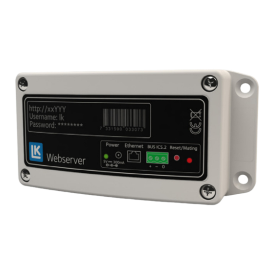
LK Webserver
Design
LK Webserver is used to access and control
LK Room Temperature Control ICS.2 and/or
LK Water Safety System WSS via the Internet or
a local network. The interface is suitable for cell
phones, tablets or computers and can be reached
via a website or an app for Android and Apple
IOS. Interface updates continually take place and
new functions will be available, see the latest
manual at www.lksystems.se/en.
LK Webserver continually logs the floor heating
system (temperatures, heat to/from etc.) to
enable optimization of the performance of the
floor heating systems. The logged data can be
retrieved and analyzed with LK Analyzer ICS.2
software which can be downloaded from the
LK Systems website.
Installation of the LK Webserver
The webserver can only be connected to the
LK Receiver 8 ICS.2 and LK Water Safety System
WSS. The webserver is placed near a room tem-
perature control if it is to be used for both floor
heating and water safety system. Otherwise it can
be located near a network socket and then com-
municate wirelessly with the master unit of the
water safety system.
The webserver can be installed in three differ-
ent ways:
1 Only for an LK Receiver 8 ICS.2, start the
installation at point 1 in the instructions below.
2 Using two webservers to create a wireless
bridge when an internet connection is not avail-
able near the receiver of the floor heating instal-
lation. Begin installation as shown below in
point 1 in the instructions.
3 Only for the LK Water Safety System WSS,
begin installation as shown below in point 11 in
the instructions.
Assembly instructions | LK Webserver
Connecting the LK Receiver 8 ICS.2 with
1
LK Webserver
An example of a system with the webserver connected by cable
to the router. The webserver is connected to both the water safety
system and room temperature control ICS.2.
1. Attach the webserver with a suitable screw.
2. Switch off the power to the LK Receiver.
3. Connection is done with a three-conductor
cable (> 0.25 mm2). Connect the LK Receiver
8 ICS.2 (Master) three-pole busbar marked-
BUS with cable to the three-pole connection
of the LK Webserver marked BUS ICS.2.
Connect pole to pole, i.e. plus [+] is connect-
ed to plus [+], minus [-] to minus [-] and zero
[0] to zero [0].
BUS cable
4. Energize the LK Receiver.
5. Connect the cable from the mains adapter to
the input Power 5 V DC input on the web-
server, connect the mains adapter to a wall
socket.
6. Connect the network cable between the
webserver's ethernet-connection and a
network socket with internet access.
EN.33.C.190.1709
1 (7)
Advertisement
Table of Contents

Summary of Contents for LK Systems LK Webserver
- Page 1 Assembly instructions | LK Webserver LK Webserver Design LK Webserver is used to access and control LK Room Temperature Control ICS.2 and/or LK Water Safety System WSS via the Internet or a local network. The interface is suitable for cell...
- Page 2 When the connection is established, the right LED will show a red solid light for a few seconds. Web interface in the LK Webserver 1. Go to the homepage below on a computer connected to the Internet or mobile device https://my.lk.nu...
- Page 3 (ab1234) and password on the then a dialogue box will appear for you to label. Click on Connect your LK Webserver. enter the Username lk and Password that is printed on the webserver.
-
Page 4: User Interface, Functions
Assembly instructions | LK Webserver User interface, functions LK Webserver makes a simpler and more trans- parent user interface to adjust system settings via the room thermostat’s menu and installation parameters. The LK Webserver always begins by searching for LK Room Temperature Control ICS.2. - Page 5 Assembly instructions | LK Webserver The desired room temperature can be set with the round buttons . Beside this displays the measured/current room temperature. There is a gear icon for each thermostat . Clicking on the icon brings you to the menu system for that specific room thermostat.
-
Page 6: Master Unit
Assembly instructions | LK Webserver 5. Update button. The webpage is automati- Control panel & Input link are shown as cally updated as soon as a change is made (Control panel) to the webpage or every tenth minute. When clicking on the gear for Control panel, the 6. -
Page 7: Cloud Service
Channel separation 25 kHz, 69 channels per-case letters as well as numbers. Modulation GFSK Cable protection class IP20 Dimensions LxHxD 137 x 62 x 31 mm EN.33.C.190.1709 LK Systems AB, Box 66, 161 26 Bromma, Sweden | www.lksystems.se 7 (7)
Need help?
Do you have a question about the LK Webserver and is the answer not in the manual?
Questions and answers