
Related Manuals for ADRF PSR-78-9533-UA


Summary of Contents for ADRF PSR-78-9533-UA
- Page 1 PSR-78-9533-UA MANUAL VERSION 0.33 3116 West Vanowen St. Burbank, CA 91505 Tel: 818-840-8131 Fax: 818-840-8138 www.adrftech.com Advanced RF Technologies, Inc.
- Page 2 Information in this document is subject to change without notice. Advanced RF Technologies, Inc. 1996-2019. All rights reserved. Please send comments to: E-Mail: info@adrftech.com Phone: (818) 840-8131 (800) 313-9345 Fax: (818) 840-8138 Address: Advanced RF Technologies, Inc. Attention: Technical Publications Department 3116 Vanowen St.
- Page 3 REVISION HISTORY Version Author Descriptions Date ADRF Initial Release 08/07/2019 0.12 ADRF update 09/11/2019 0.22 ADRF B9B Update 08/04/2020 0.23 ADRF updfate 09/04/2020 0.33 ADRF U-Type updfate 09/23/2021 CHANGE LIST Version Change list Contents Advanced RF Technologies, Inc.
-
Page 4: Table Of Contents
3.3.3 RF ................................ 21 3.3.4 Annunciator ............................21 3.3.5 Battery Backup Terminal ........................22 This port connects to the ADRF-BBS/BBL-24 (24V battery backup unit) via a dedicated cable provided by the ADRF............................. 22 3.3.6 Grounding ............................23 Alarms ................................24 Message Board Alarms and Notifications .................... - Page 5 7.2.4 AAI ..............................38 7.2.5 Repeater Info / Repeater Location / Technical Support / Installer Contact Info ........ 39 Control Tab ..............................40 7.3.1 General Settings ..........................41 7.3.1.1 Emergency Power Off Switch Support ....................41 7.3.2 System ..............................41 7.3.3 Manual Gain Control ..........................
- Page 6 10.4 ADRF-BBS-U-24 / ADRF-BBL-U-24 Runtime Calculations ................54 PSR-78-9533-U (Dual Band) w/ (1) ADRF-BBL-U-24 ....................55 PSR-78-9533-U (Dual Band) w/ (2) ADRF-BBS-U-24 + ADRF-BBX-U-CBL-21P .............. 55 PSR-78-9537-U (Dual Band) w/ (1) ADRF-BBL-U-24 ........오류! 책갈피가 정의되어 있지 않습니다. 10.5 Warranty & Certificates ..........................55 anical Drawing..............................56 Appendix ................................
- Page 7 Figure 5-32 Help ..............................51 PSR-78-9533-X Mechanical Drawing ........ 오류! 책갈피가 정의되어 있지 않습니다. Figure 9-1 PSR-78-9533-UA Mechanical Drawing ......오류! 책갈피가 정의되어 있지 않습니다. Figure 9-2 PSR-ANN Annunciator Mechanical Drawing ..... 오류! 책갈피가 정의되어 있지 않습니다. Figure 9-3 TABLES Table 1-1 Parts List .............................
- Page 8 The following is a list of abbreviations and terms used throughout this document. Abbreviation/Term Definition Automatic Gain Control Automatic Level Control AROMS ADRF Repeater Operation and Management System Bi-Directional Amplifier Base Transceiver Station CDMA Code Division Multiple Access Crest Factor Reduction...
-
Page 9: Introduction
1. 5INTRODUCTION PSR-78-9533-UA bi-directional amplifiers (BDAs) extend the coverage area of radio communications in buildings and RF shadow environments. These units feature low noise figure and wide dynamic range and are certified to UL 2524. The PSR-78-9533-UA is a revolutionary digital public safety repeater designed to protect the lives of first responders and building occupants. -
Page 10: Parts List
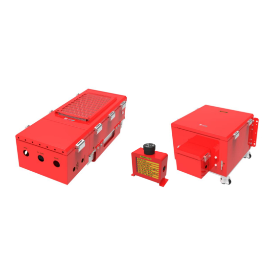
Parts List Table 1-1 Parts List Label Quantity Description PSR-78-9533-UA Wall Mount Bracket Mounting Bracket Template AAI Alarm Cable Ethernet Cable (Crossover) Anchor Bolt PSR-ANN (Annunciator Panel) Figure 1-1 PSR-78-9533-UA Repeater Parts List Advanced RF Technologies, Inc. -
Page 11: Quick View
Quick View Ground Terminal Figure 1-2 PSR-78-9533-UA External Ground Terminal Donor Port Server Port (4.3-10 Female) (4.3-10 Female) Sever CPL (DL Output Donor CPL (UL Output Monitor Port, -30dB) Monitor Port, -30dB) AAI Alarm Port Battery backup Port AC Input Port... -
Page 12: Figure 1-2 Psr-Ann Annunciator
Audible Alarm Speaker Alarm Indicator Lights Data/Power Port Repeater / Wall Mount Bracket Figure 1-4 PSR-ANN Annunciator Advanced RF Technologies, Inc. -
Page 13: Warnings And Hazards
Warnings and Hazards WARNING! ELECTRIC SHOCK Opening the PSR-78-9533-UA could result in electric shock and may cause severe injury. WARNING! DAMAGE TO REPEATER Operating the PSR-78-9533-UA with antennas in very close proximity facing each other could lead to severe damage to the repeater. - Page 14 Preclude indications that Home/ personal use are prohibited. Use of unauthorized antennas, cables, and/or coupling devices not conforming with ERP/EIRP is prohibited. FCC Part 15.21 Any changes or modifications not expressly approved by the party responsible for compliance could void the user's authority to operate this equipment. FCC Part 15 Class A NOTE: This equipment has been tested and found to comply with the limits for a Class A digital device, pursuant to part 15 of the FCC Rules.
- Page 15 Regulatory Warning Statement FCC RF Radiation Exposure Statement: This equipment complies with FCC RF radiation exposure limits set forth for an uncontrolled environment. This equipment should be installed and operated with a minimum distance of 210 cm between the radiator and your body. This transmitter must not be co-located or operating in conjunction with any other antenna or transmitter.
-
Page 16: Installation
Wiring Compartment The bottom of the PSR-78-9533-UA is a wiring compartment with pre-cut holes. These holes are designed to be used in conjunction with conduit hubs to prevent water ingress. A total of 6 pre-cut holes are available to use for the various cables that will be needed for the proper operation of the repeater. -
Page 17: Wire Terminals
Wire Terminals Non-power limited cables such as the AC power line and the DC battery line shown below in red must be separated by ¼” from power limited cables such as the donor/server, ext. alarm, and annunciator lines shown below in black. To maintain the ¼” spacing, route the annunciator line above the server line as shown in the picture below. -
Page 18: Overview
AC_G Ground 12AWG 3. OVERVIEW PSR-78-9533-UA LED indicator lights are located on the inside of the repeater towards the bottom. Below the LED indicators is a button that is used to trigger the door open alarm. Figure 3-1 LED Panel... -
Page 19: Cable Connection
Remote IP: 192.168.63.5 (Default IP, but can be modified in Host mode) Figure 3-2 Host/Remote Switch Cable Connection 3.3.1 AC Power The AC Terminal is located at the bottom of the wiring compartment on the opposite side of the wiring compartment door. -
Page 20: External Alarm
3.3.2 External Alarm Figure 3-3 External Alarm Port This port should be connected only to the fire alarm control panel. Table 3-1 External Alarm Port Pin Description ADRF External Alarm Box Alarm Color Pin Description (24 pins) Pin Description Type... -
Page 21: Annunciator
Blue 3.3.3 RF Figure 3-4 RF Ports The RF connections are made via two 4.3-10 female connectors. The RF connector labeled “DONOR” must be connected to the antenna pointing towards the base station. The DONOR port can receive both 700 and 800MHz public safety signals. -
Page 22: Battery Backup Terminal
Battery Backup Port (4-pin Female) When the ADRF-BBS/BBL-24 is connected to the repeater, the battery switch on the PSU must be switched to the ON position. This will enable the repeater to charge the ADRF-BBS/BBL-24 battery backup unit when AC power is present. -
Page 23: Grounding
(WARNING: The circuit breaker switch on the ADRF-BBS/BBL-24 must be set to OFF before connecting it to the PSR-78-9533-UA to prevent damage to the repeater or the ADRF-BBS/BBL-24 and personal injury.) Note: Please contact ADRF Technical Support for assistance if you are unfamiliar with the installation procedure of the battery box. -
Page 24: Alarms
4. ALARMS Message Board Alarms and Notifications Table 4-1 Message Board Alarms and Notifications Alarm Alarm Description Trigger Condition AC Input is outside of AC Fail The power supply is not operating within specs. (4 seconds) operating range DC Output is outside of DC Fail The power supply is not operating within specs. -
Page 25: External Alarms
4.2 External Alarms The PSR-78-9533-UA supports dry contact alarms and can be connected to a fire alarm control panel. The user can program the repeater to either create an open or closed circuit when an alarm is present in the system. -
Page 26: Installation
5.1.2 PSR-ANN Annunciator Installation The PSR-ANN annunciator box has been designed to either mount on top of the PSR-78-9533-UA repeater or can also be wall mounted separately. By default, the mounting bracket is configured to mount to the top of the repeater with the mounting bracket at the bottom of the PSR-ANN annunciator box. -
Page 27: Figure 4-2 Psr-Ann Repeater Mount
Figure 5-2 PSR-ANN Repeater Mount Figure 5-3 PSR-ANN Wall Mount Advanced RF Technologies, Inc. -
Page 28: Antenna Separation/Isolation
Antenna Separation/Isolation The separation between the donor and server antennas is necessary to prevent oscillation. Oscillation occurs when the signal entering the system continually re-enters, due to the lack of separation between the donor and server antennas. In other words, the signal is being fed back into the system. This creates a constant amplification of the same signal. - Page 29 DO NOT APPLY AC POWER TO THE BDA UNTIL CABLES ARE CONNECTED TO BOTH PORTS OF THE BDA AND THE ANTENNAS. 1. To mount on a wall. Using appropriate screws and anchors attach the BDA to the wall at the four mounting holes.
-
Page 30: Adrf-Bbl/Bbs-U Installation
4. The brackets on the back of the ADRF-BBL/BBS-U unit can be used to secure to the wall ONLY when it is stationed on the floor. Due to the total weight of the ADRF-BBL/BBS-U w/ batteries, it CANNOT be wall mounted off the ground. - Page 31 7. On the PSR-78-9533/9537-U, verify that both AC and BATT switches have been set to the OFF position. 8. Use the provided battery backup cable from the ADRF-BBL-U and connect the wires to the terminal block located inside of the wiring compartment of the PSR-78-9533/9537-U.
- Page 32 9. Install a conduit hub connector that can support 7/8” onto the PSR-78-9533-UA hole labeled BATTERY and snake the cable through the conduit. 10. Install a conduit hub connector that can support 7/8” onto the ADRF-BBL-U hole labeled BATTERY.
- Page 33 13. On the PSR-78-9533-UA, flip the POWER and BATT switch to the ON position. 14. On the ADRF-BBL-U-24, set the circuit breaker to the ON position. Advanced RF Technologies, Inc.
-
Page 34: Psr-78-9533-U/9537-U Web-Gui Setup Introduction
PSR-78-9533-UA WEB-GUI SETUP INTRODUCTION The Web-GUI allows the user to communicate with the repeater locally. To connect to the repeater locally, you will need a laptop with an Ethernet port and an RJ-45 crossover cable. NOTICE TO USERS, INSTALLERS, AUTHORITIES HAVING JURISDICTION, AND OTHER INVOLVED PARTIES This product incorporates field-programmable software. -
Page 35: Psr-78-9533-Ua Web-Gui Setup
PSR-78-9533-UA WEB-GUI SETUP The Web-GUI allows the user to communicate with the repeater either locally or remotely. To connect to the repeater locally, you will need a laptop with an Ethernet port and an RJ-45 crossover cable. To connect to the repeater remotely, you will need to have an active internet connection via an external modem or LAN. -
Page 36: Status Tab
Status Tab Figure 7-3 Status Tab Advanced RF Technologies, Inc. -
Page 37: Band Info
7.2.1 Band Info The Band Info section displays frequency information along with the corresponding bandwidths that have been set from the Install tab. Input levels for each channel are also displayed in this section. Figure 7-4 Status Tab – Band Info Display 7.2.2 Power &... -
Page 38: Alarms
7.2.3 Alarms This section displays the alarm status for System alarms, RF Alarms, and Power alarms. If an alarm is present in the system, then the color of the alarm tab will change according to the type of failure. Figure 7-2 Status Tab –... -
Page 39: Repeater Info / Repeater Location / Technical Support / Installer Contact Info
Repeater Info: Displays the serial number, latitude, longitude, firmware version, and Web-GUI version Repeater Location: Displays the address where the repeater is installed Technical Support: Displays ADRF’s Technical Support contact information Installer Contact Info: Displays the installer’s name, phone, and e-mail address Advanced RF Technologies, Inc. -
Page 40: Control Tab
Control Tab Figure 7-6 Control Tab Advanced RF Technologies, Inc. -
Page 41: General Settings
7.3.1.1 Emergency Power Off Switch Support The PSR-78-9533-UA now support the ability to connect an extern power switch to turn on/off the high power amplifier via our Alarm Input dry contact pins. This Emergency Power Off (EPO) function is an optional feature that is only active when the function is enabled. -
Page 42: Manual Gain Control
7.3.3 Manual Gain Control Figure 7-10 Control Tab – Manual Gain Control DL/UL Gain: Gain levels of the repeater can be specified here DL/UL ALC Level: Prevents the output power from exceeding the specified value DL/UL Output ALC Offset: If any ALC attenuation has been applied, the system will release this attenuation when the signal level drops by the specified level ... -
Page 43: Install Tab
Install Tab Figure 7-12 Install Tab Advanced RF Technologies, Inc. -
Page 44: Technology
7.4.1 Technology This section allows the user to set the repeater mode to either use PS700, PS800, or PS700+PS800. Figure 7-13 Install Tab – Technology The following choices are available from the drop-down menu: N – PS700 (16ch) + PS800 (16ch) (758-861MHz) ... -
Page 45: Snmp
Channel Center Frequency: The user can input the center frequency of the pass-band. Bandwidth: Allows the user to select the desired bandwidth for the passband. Choices for wideband frequencies include 3, 5, or 10 MHz. Narrowband choices include 6.25, 12.5, 25.0, 75.0 and 200 kHz. The required frequency spacing between channels is 4x the bandwidth from center to center. -
Page 46: Aai Input
7.4.6 AAI Input The PSR-78-9533-UA can accept a dry contact input alarms. The alarm can be labeled in this section. Once the alarm is labeled, it will show up in the system with the new custom names on the Status tab. This feature is only available if the Emergency Power Off switch function is not being utilized. -
Page 47: System
System The System tab allows the user to perform firmware updates, upload closeout packages, view any changes to the system, backup existing configuration, add/remove user accounts, and change the login credentials of the Administrator. 7.5.1 System: Account 7.5.1.1 System: Account – Account Management The Account Management section allows the Administrator to delete any user accounts. -
Page 48: System - Snmp
7.5.2 System – SNMP This section displays The SNMP section allows the user to define the parameters for SNMP v1, v2c, and v3. Community strings for v1/v2c can be specified from here and SNMP user account can be created/deleted from this section. -
Page 49: System - Update
Figure 7-25 System: Logs 7.5.4 System – Update To perform a firmware update, click on the Update tab and the following screen will appear. Figure 7-26 System: Update Click on the Choose File button and locate the firmware file. ... -
Page 50: System - Backup / Restore
Figure 7-27 System: Update is Complete Popup Message 7.5.5 System – Backup / Restore The Backup / Restore section allows the user to save the settings of the repeater. To perform the backup, click on the Backup button and you will be prompted to save the backup file. To restore the settings to the system, click on Choose File button, select the backup file, and click the Restore button. -
Page 51: Help
Turn the circuit breaker to the off position and unscrew the fuse holder to inspect the fuse i. A spare fuse is included with the purchase of the ADRF-BBL-U and can be used to replace the fuse if needed ... -
Page 52: Preventive Measures For Optimal Operation
Do not detach any cables to the repeater unless repair of respective components is necessary. 9. WARRANTY AND REPAIR POLICY General Warranty The PSR-78-9533-UA carries a Standard Warranty period of two (2) years unless indicated otherwise on the package or in the acknowledgment of the purchase order. Limitations of Warranty Your exclusive remedy for any defective product is limited to the repair or replacement of the defective product. -
Page 53: Specifications
BW, <10us@200KHz BW Power Supply 100 -240 VAC, 60 Hz (Free Voltage) Optional battery backup <150 W / < 222 W Power Consumption (PSR-78-9533-UA / 9537) Max RF Input Power without overdrive -20dBm No damage Max Input Power +10 dBm Impedance 50 Ω... -
Page 54: Mechanical Specifications
IP66 10.3 Power Specifications Table 10-3 Power Specifications Parameters Specifications Comments PSR-78-9533-UA: 100 – 240 VAC, 50/60 Hz, 1.93-0.84A Repeater Rating or 27VDC, 4.85A (Battery Port Only) Annunciator Rating 28VDC Nominal, 108.3mA AC Supply Protection Fuse & Circuit Protector T6.3L250V... -
Page 55: Psr-78-9533-U (Dual Band) W/ (1) Adrf-Bbl-U-24
PSR-78-9533-UA (Dual Band) w/ PSR-78-9533-UB (Dual Band) w/ (1) ADRF-BBL-U-24 (2) ADRF-BBS-U-24 + ADRF-BBX-U-CBL-21P Repeater Repeater DC Power Consumption (W) – 127.16 DC Power Consumption (W) – 127.16 DC Voltage (V) – 24.02 DC Voltage (V) – 24.02 ... -
Page 56: Anical Drawing
11. ANICAL DRAWING Figure 11-1 PSR-78-9533-U Mechanical Drawing Advanced RF Technologies, Inc. - Page 57 Figure 11-2 PSR-ANN Annunciator Mechanical Drawing Advanced RF Technologies, Inc.
- Page 58 Figure 11-3 ADRF-BBL-U Mechanical Drawing Advanced RF Technologies, Inc.
- Page 59 Figure 11-4 ADRF-BBS-U Mechanical Drawing Advanced RF Technologies, Inc.
-
Page 60: Appendix
12. APPENDIX 12.1 Shutdown Retry Logic The function of the built-in shutdown routine is to protect the repeater from any further damage from a hard- fail that the system may be experiencing. Within 5 seconds of a hard-fail alarm being detected, the repeater will start the shutdown routine. The repeater will shut down by powering off the HPAs (high-powered amplifiers) for 30 seconds.
Need help?
Do you have a question about the PSR-78-9533-UA and is the answer not in the manual?
Questions and answers