
Related Manuals for ADRF PSR-78-8527


Summary of Contents for ADRF PSR-78-8527
- Page 1 PSR-78-8527 User Manual Version 0.1 3116 West Vanowen St. Burbank, CA 91505 Tel: 818-840-8131 Fax: 818-840-8138 www.adrftech.com Advanced RF Technologies, Inc.
- Page 2 Information in this document is subject to change without notice. Advanced RF Technologies, Inc. 1996-2020. All rights reserved. Please send comments to: E-Mail: info@adrftech.com Phone: (818) 840-8131 (800) 313-9345 Fax: (818) 840-8138 Address: Advanced RF Technologies, Inc. Attention: Technical Publications Department 3116 Vanowen St.
- Page 3 REVISION HISTORY Version Author Descriptions Date YH Ko Initial Release 09/15/2020 CHANGE LIST Version Change list Contents Advanced RF Technologies, Inc.
-
Page 4: Table Of Contents
Repeater Installation ............................23 Installation Procedures ..........................23 5.1.1 Wall Mount Procedure ........................23 Antenna Separation/Isolation ........................24 Maintenance Guide for PSR-78-8527 Repeater ....................26 Periodic Inspection Checklist ........................26 Preventive Measures for Optimal Operation .................... 26 6.2.1 Recommendations ..........................26 6.2.2 Precautions ............................ - Page 5 FIGURES Figure 1-1 PSR-78-8527 Repeater Parts List ......................8 Figure 1-2 PSR-78-8527 External Ground Terminal ....................9 Figure 1-3 PSR-78-8527 Quick View (Bottom) ....................... 9 Figure 2-1 Conduit holes ............................14 Figure 3-1 LED Panel ............................15 Figure 3-2 AC On/Off Switch ..........................16 Figure 3-3 AC Connector ............................
- Page 6 The following is a list of abbreviations and terms used throughout this document. Abbreviation/Term Definition Automatic Gain Control Automatic Level Control AROMS ADRF Repeater Operation and Management System Bi-Directional Amplifier Base Transceiver Station CDMA Code Division Multiple Access Crest Factor Reduction...
-
Page 7: Introduction
1. INTRODUCTION PSR-78-8527 bi-directional amplifiers (BDAs) extend the coverage area of radio communications in buildings and RF shadow environments. Product Features Alarming output to supervised circuits for: antenna, amplifier, power supply, battery, and charger failure Up to 85dB of gain and up to 27 dBm downlink output power per band and up to 24 dBm uplink... -
Page 8: Parts List
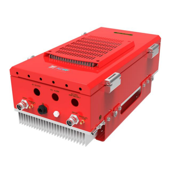
Parts List Table 1-1 Parts List Label Quantity Description PSR-78-8527 Wall Mount Bracket Mounting Bracket Template AAI Alarm Cable Battery Cable AC Cable Ethernet Cable (Crossover) Anchor Bolt Figure 1-1 PSR-78-8527 Repeater Parts List Advanced RF Technologies, Inc. -
Page 9: Quick View
Quick View Ground Terminal Figure 1-2 PSR-78-8527 External Ground Terminal AAI Alarm AC Input Conduit Hole Conduit Hole Battery Backup Conduit Hole Donor CPL (UL Output Monitor Port, -30dB) Sever CPL (DL Output Monitor Port, -30dB) Donor Port (4.3-10 Female) Server Port (4.3-10 Female) -
Page 10: Warnings And Hazards
Warnings and Hazards WARNING! ELECTRIC SHOCK Opening the PSR-78-8527 could result in electric shock and may cause severe injury. WARNING! EXPOSURE TO RF Working with the repeater while in operation, may expose the technician to RF electromagnetic fields that exceed FCC rules for human exposure. Visit the FCC website at www.fcc.gov/oet/rfsafety... - Page 11 WARRANTY Opening or tampering the PSR-78-8527 will void all warranties. Lithium Battery: CAUTION. RISK OF EXPLOSION IF BATTERY IS REPLACED BY INCORRECT TYPE. DISPOSE OF USED BATTERIES ACCORDING TO INSTRUCTIONS. CR2032 BATTERY MUST BE USED AS A REPLACEMENT ON THE CONTROL BOARD WHICH IS USED FOR REAL-TIME CLOCK (RTC) BACKUP.
- Page 12 FCC Part 90 Class B WARNING. THIS is NOT a CONSUMER device. It is designed for installation by FCC LICENSEES and QUALIFIED INSTALLERS. You MUST have an FCC LICENSE or express consent of an FCC Licensee to operate this device. You MUST register Class B signal boosters (as defined in 47 CFR 90.219) online at www.fcc.gov/signal-boosters/registration.
- Page 13 RSS-GEN, Sec. 7.1.2– (detachable antennas) This radio transmitter (identify the device by certification number, or model number if Category II) has been approved by Industry Canada to operate with the antenna types listed below with the maximum permissible gain and required antenna impedance for each antenna type indicated. Antenna types not included in this list, having a gain greater than the maximum gain indicated for that type, are strictly prohibited for use with this device.
-
Page 14: Installation
2. INSTALLATION Cable Installation The bottom of the PSR-78-8527 has three conduit holes. Table 2-1 Conduit hole size and labels Silkscreen Label Location Diameter AC 100-240V LEFT 22.2mm (7/8”) Ext. ALARM CENTER 22.2mm (7/8”) BATTERY ADRF-BBU ONLY RIGHT 22.2mm (7/8”) -
Page 15: Overview
3. OVERVIEW PSR-78-8527 LED indicator lights are located on the inside of the repeater towards the bottom. Below the LED indicators is a button that is used to trigger the door open alarm. Figure 3-1 LED Panel Table 3-1 LED Specifications... -
Page 16: Cable Connection
Cable Connection 3.2.1 AC Power Figure 3-2 AC On/Off Switch The AC Power on/off switch is on the left-hand of the PSU which is located inside of the repeater. Figure 3-3 AC Connector Figure 3-4 AC Terminal of the PSU The AC terminal is at the left-hand side of the PSU. -
Page 17: External Alarm
External Alarm port should be connected only to the fire alarm control panel. The default length of the cable that is provided to connect to an FACP is 6m (19.5ft). The EXT alarm wiring cannot exceed 30m (98.5ft). Table 3-2 External Alarm Description ADRF External Alarm Box Color Pin Description (24 pins) Alarm Type... -
Page 18: Figure 3-7 Rf Ports
Battery charger failure_N 7-NEG Output Blue 8-POS Output Purple Summary Alarm_P 8-NEG Output Purple Summary Alarm_N 9-POS Output Grey Donor Antenna Disconnect_P 9-NEG Output Grey Donor Antenna Disconnect_N 10-POS Output White Oscillation Alarm_P 10-NEG Output White Oscillation Alarm_N Alarm-In Input Light Blue GND(Alarm-In) Input... -
Page 19: Battery Backup Port
Battery Backup Cut-out hole (0.87 in) When the ADRF-BBS/BBL-24 is connected to the repeater, the battery switch on the PSU must be switched to the ON position. This will enable the repeater to charge the ADRF-BBS/BBL-24 battery backup unit when AC power is present. -
Page 20: Grounding
3.2.5 Grounding The grounding terminal is located at the lower right-hand side of the BDA. A grounding cable should be properly connected before powering on the equipment. Figure 3-10 Ground Cable Terminal Ground terminals located on the side of the repeater and can support a ground cable up to 1.25mm² (16AWG) in diameter and should be permanently connected to a grounding bar. -
Page 21: Alarms
4. ALARMS Message Board Alarms and Notifications Table 4-1 Message Board Alarms and Notifications Alarm Alarm Description Trigger Condition AC Input is outside of AC Fail The power supply is not operating within specs. operating range DC Output is outside of DC Fail The power supply is not operating within specs. -
Page 22: External Alarms
External Alarms The PSR-78-8527 supports dry contact alarms and can be connected to a fire alarm control panel (FACP). The user can program the repeater to either create an open or closed circuit when an alarm is present in the system. The repeater must be installed within 30m (98.4ft) from the FACP. -
Page 23: Repeater Installation
Verify that the PSR-78-8527 and mounting holes are in good condition Place the PSR-78-8527 mounting bracket template up against the wall and mark off mounting holes Drill the appropriate size holes and install the included wall anchors ... -
Page 24: Antenna Separation/Isolation
70dB, then isolation of 85dB or greater is required. In the same manner, to utilize the maximum gain of 85dB of the PSR-78-8527, antenna isolation of at least 100dB is required. Advanced RF Technologies, Inc. - Page 25 DO NOT APPLY AC POWER TO THE BDA UNTIL CABLES ARE CONNECTED TO BOTH PORTS OF THE BDA AND THE ANTENNAS. Prior to equipment use, the device must be registered with the FCC. This can be done through the FCC’s website at https://signalboosters.fcc.gov/signal-boosters 1.
-
Page 26: Maintenance Guide For Psr-78-8527 Repeater
Do not detach any cables to the repeater unless repair of respective components is necessary. 7. WARRANTY AND REPAIR POLICY General Warranty The PSR-78-8527 carries a Standard Warranty period of two years unless indicated otherwise on the package or in the acknowledgment of the purchase order. Limitations of Warranty Your exclusive remedy for any defective product is limited to the repair or replacement of the defective product. -
Page 27: Return Material Authorization (Rma)
Return Material Authorization (RMA) No product may be returned directly to Advanced RF Technologies, Inc. without first getting approval from Advanced RF Technologies, Inc. If it is determined that the product may be defective, you will be given an RMA number and instructions on how to return the product. -
Page 28: Specifications
8. SPECIFICATIONS System Specifications Table 8-1 System Specifications Specifications Parameters Remarks 758-768 (FCC & IC) 788-798 (FCC & IC) Frequency Range 769-775 (FCC only) 799 -805 (FCC only) (MHz) 854-861 (FCC only) 809-816 (FCC only) In case of 700/800 simultaneous output, the Composite Output Power 27 dBm 24 dBm... -
Page 29: Mechanical Drawing
9. MECHANICAL DRAWING Figure 9-1 PSR-78-8527 Mechanical Drawing Advanced RF Technologies, Inc.
Need help?
Do you have a question about the PSR-78-8527 and is the answer not in the manual?
Questions and answers