
Related Manuals for ADRF PSR-78-9537


Summary of Contents for ADRF PSR-78-9537
- Page 1 PSR-78-9537 MANUAL VERSION 0.1 3116 West Vanowen St. Burbank, CA 91505 Tel: 818-840-8131 Fax: 818-840-8138 www.adrftech.com Advanced RF Technologies, Inc.
- Page 2 Information in this document is subject to change without notice. Advanced RF Technologies, Inc. 1996-2016. All rights reserved. Please send comments to: E-Mail: info@adrftech.com Phone: (818) 840-8131 (800) 313-9345 Fax: (818) 840-8138 Address: Advanced RF Technologies, Inc. Attention: Technical Publications Department 3116 Vanowen St.
- Page 3 REVISION HISTORY Version Author Descriptions Date ADRF Initial Release 05/04/2018 CHANGE LIST Version Change list Contents Advanced RF Technologies, Inc.
-
Page 4: Table Of Contents
Installation ................................ 26 Installation Procedures ..........................26 4.1.1 Wall Mount Procedure ........................26 Antenna Separation/Isolation ........................27 PSR-78-9537 Web-GUI Setup ..........................29 Repeater/PC Connection Using Web-GUI ....................29 Status Tab ..............................30 5.2.1 Band Info ............................31 5.2.2 Power & Gain ............................31 5.2.3 Alarms .............................. - Page 5 5.5.3 System – Update ..........................42 5.5.4 System – Backup & Restore ........................ 42 Help ................................43 Logout ................................ 43 Maintenance Guide for PSR-78-9537 Repeater ....................43 Periodic Inspection Checklist ........................43 Preventive Measures for Optimal Operation .................... 43 6.2.1 Recommendations ..........................43 6.2.2 Precautions ............................
- Page 6 FIGURES Figure 1-1 PSR-78-9537 Repeater Parts List ......................10 Figure 1-2 PSR-78-9537 Quick View (Bottom) ..................... 11 Figure 2-1 LED Panel ............................17 Figure 2-2 Host/Remote Switch ........................... 17 Figure 2-3 AC Input Port ............................18 Figure 2-4 AC On/Off Switch ..........................18 Figure 2-5 External Alarm port ..........................
- Page 7 TABLES Table 1-1 Parts List ............................. 10 Table 2-1 LED Specifications ..........................17 Table 2-2 External Alarm Port Pin Description ....................19 Table 3-1 Message Board Alarms and Notifications................... 23 Table 3-2 Alarms ..............................23 Table 8-1 Electrical Specifications ........................45 Table 8-2 Mechanical Specifications ........................
- Page 8 The following is a list of abbreviations and terms used throughout this document. Abbreviation/Term Definition Automatic Gain Control Automatic Level Control AROMS ADRF Repeater Operation and Management System Bi-Directional Amplifier Base Transceiver Station CDMA Code Division Multiple Access Crest Factor Reduction...
-
Page 9: Introduction
1. INTRODUCTION PSR-78-9537 bi-directional amplifier (BDA) extends the coverage area of radio communications in buildings and RF shadow environments. The unit features low noise figure and wide dynamic range. 1.1 Highlights Supports both 700MHz and 800MHz Public Safety Frequencies in a single repeater ... -
Page 10: Parts List
Parts List Table 1-1 Parts List Label Quantity Description PSR-78-9537 Wall Mount Bracket Mounting Bracket Template AAI Alarm Cable AC Power Cable Ethernet Cable (Crossover) Anchor Bolt Ground Cable Documentation CD Figure 1-1 PSR-78-9537 Repeater Parts List Advanced RF Technologies, Inc. -
Page 11: Quick View
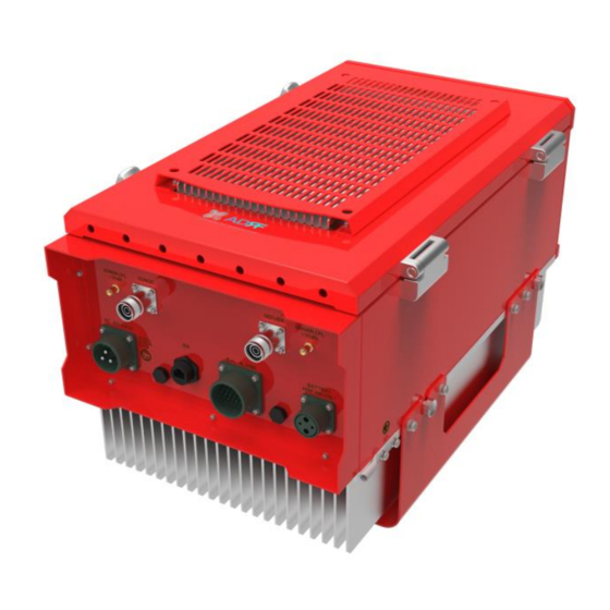
Sever CPL (DL Output Donor CPL (UL Output Monitor Port,-30dB) Monitor Port, -30dB) AAI Alarm Port Ethernet Port (RJ-45) ADRF-BBU AC Input Port Battery Port Air Vent Hole Heat Sink Figure 1-2 PSR-78-9537 Quick View (Bottom) Advanced RF Technologies, Inc. -
Page 12: Warnings And Hazards
Warnings and Hazards WARNING! ELECTRIC SHOCK Opening the PSR-78-9537 could result in electric shock and may cause severe injury. WARNING! EXPOSURE TO RF Working with the repeater while in operation, may expose the technician to RF electromagnetic fields that exceed FCC rules for human exposure. Visit the FCC website at www.fcc.gov/oet/rfsafety... - Page 13 Lithium Battery: CAUTION. RISK OF EXPLOSION IF BATTERY IS REPLACED BY INCORRECT TYPE. DISPOSE OF USED BATTERIES ACCORDING TO INSTRUCTIONS. Ethernet Instructions: This equipment is for indoor use only. All cabling should be limited to inside the building. Preclude indications that Home/ personal use are prohibited. Use of unauthorized antennas, cables, and/or coupling devices not conforming with ERP/EIRP is prohibited.
- Page 14 FCC Part 90 Class A WARNING. THIS is NOT a CONSUMER device. It is designed for installation by FCC LICENSEES and QUALIFIED INSTALLERS. You MUST have an FCC LICENSE or express consent of an FCC Licensee to operate this device. You MUST register Class B signal boosters (as defined in 47 CFR 90.219) online at www.fcc.gov/signal-boosters/registration.
- Page 15 RSS-GEN, Sec. 7.1.2– (detachable antennas) This radio transmitter (identify the device by certification number, or model number if Category II) has been approved by Industry Canada to operate with the antenna types listed below with the maximum permissible gain and required antenna impedance for each antenna type indicated. Antenna types not included in this list, having a gain greater than the maximum gain indicated for that type, are strictly prohibited for use with this device.
- Page 16 Part 90.635 requirement Antennas must be installed in accordance with FCC 90.635. With 17 dBi gain antennas the height of the antenna above average terrain (HAAT) must not exceed 59.96 m. For different gain antennas refer to the relevant rules. ◈LABEL WARNING◈...
-
Page 17: Overview
2. OVERVIEW PSR-78-9537 LED indicator lights are located on the inside of the repeater towards the bottom. Below the LED indicators is a button that is used to trigger the door open alarm. Figure 2-1 LED Panel Table 2-1 LED Specifications... -
Page 18: Cable Connection
Cable Connection 2.3.1 AC Power AC power is accepted through a standard 3-wire male plug (MS3106A-22-2S) with phase, neutral, and ground leads. The AC power is wired to a high-efficiency DC switching power supply which is UL approved. The AC port is located at the bottom of the repeater and has a free range input of 100-240V AC. Figure 2-3 AC Input Port AC On/Off switch... -
Page 19: External Alarm
2.3.2 External Alarm Figure 2-5 External Alarm port This port should be connected only to the fire alarm control panel. Table 2-2 External Alarm Port Pin Description ADRF External Alarm Alarm Type (24 pins) Pin Description Box Pin description 1-POS... -
Page 20: Figure 2-6 Rf Ports
2.3.3 RF Figure 2-6 RF ports The RF connections are made via two 4.3-10 female connectors. The RF connector labeled “DONOR” must be connected to the antenna pointing towards the base station. The DONOR port can receive both 700 and 800MHz public safety signals. -
Page 21: Back Up Battery Port
Battery Backup Port If an ADRF-BBS/BBL-24 is connected to the repeater, the battery switch on the PSU must be switched to the ON position. This will enable the repeater to charge the ADRF-BBS/BBL-24 battery backup unit when AC power is present. -
Page 22: Grounding
2.3.6 Ethernet Port The GUI port can be used to communicate directly with the PSR-78-9537 using an RJ-45 crossover cable. The weatherproof cap must first be unscrewed to gain access to the GUI port. -
Page 23: Alarms
3. ALARMS Message Board Alarms and Notifications Table 3-1 Message Board Alarms and Notifications Parameters Remark AC Fail AC Input is outside of operating range DC Fail DC Output is outside of operating range Temperature Module is above/below the normal operating temperature Current PSU is providing more than the max current System Halt... -
Page 24: External Alarms
External Alarms The PSR-78-9537 supports dry contact alarms and can be connected to a fire alarm control panel. The user can program the repeater to either create an open or closed circuit when an alarm is present in the system. -
Page 25: External Alarm Input Interface
External Alarm Name Set Condition DL Return Power Hard Fail DL/UL Over Power Hard Fail DL/UL Input Overload Hard Fail Over Current Hard Fail Over Temperature Hard Fail System Component Malfunction DSP Hard Fail Out-band Overload Hard Fail 3.3.2 External Alarm Input interface User Alarm Input Port External Alarm In User Alarm... -
Page 26: Installation
Verify that the PSR-78-9537 and mounting hole are in good condition Place the PSR-78-9537 mounting bracket template up against the wall and mark off mount holes Drill the appropriate size holes and install the included wall anchors ... -
Page 27: Antenna Separation/Isolation
50dB, then an isolation of 65dB or greater is required. In the same manner, to utilize the maximum gain of 95dB of the PSR-78-9537, an isolation of at least 110dB is required. Advanced RF Technologies, Inc. - Page 28 DO NOT APPLY A.C. POWER TO THE BDA UNTIL CABLES ARE CONNECTED TO BOTH PORTS OF THE BDA AND THE ANTENNAS. 1. To mount on a wall. Using appropriate screws and anchors and attach the BDA to the wall at the four mounting holes.
-
Page 29: Psr-78-9537 Web-Gui Setup
PSR-78-9537 WEB-GUI SETUP The Web-GUI allows the user to communicate with the repeater either locally or remotely. To connect to the repeater locally, you will need a laptop with an Ethernet port and an RJ-45 crossover cable. To connect to the repeater remotely, you will need to have an active internet connection via an external modem or LAN. -
Page 30: Status Tab
Status Tab Figure 5-2 Status Tab Advanced RF Technologies, Inc. -
Page 31: Band Info
5.2.1 Band Info The Band Info section displays frequency information along with the corresponding bandwidths that have been set from the Install tab. Input levels for each channel are also displayed in this section. Figure 5-3 Band Info Display 5.2.2 Power & Gain This section displays the Input, Gain, and Output for both downlink and uplink. -
Page 32: Alarms
Repeater Info: Displays the serial number, latitude, longitude, firmware version, and Web-GUI version Repeater Location: Displays the address where the repeater is installed Technical Support: Displays ADRF’s Technical Support contact information Installer Contact Info: Displays the installer’s name, phone, and e-mail address Note: Once successfully logged in, the repeater model name and the site/cascade ID will be displayed on the top of all the windows (except for the Main Window). -
Page 33: Control Tab
Control Tab Figure 5-7 Control page Advanced RF Technologies, Inc. -
Page 34: General Setting
5.3.1 General Setting The General Setting section allows the user to enable/disable amplifiers and the ALC routine. Figure 5-8 General Setting ALC ON: Enables or disables Automatic Level Control (ALC) PSR 700 DL HPA On: Enables or disables the Downlink High Power Amplifier (HPA) for 700MHz PS PSR 800 DL HPA On: Enables or disables the Downlink High Power Amplifier (HPA) for 800MHz PS PSR 700+800 UL HPA On: Enables or disables the Uplink High Power Amplifier (HPA) for 700+800MHz PS To enable/disable any of the settings, click on the checkbox and click the Apply button. -
Page 35: Alarm Settings
5.3.4 Alarm Settings Figure 5-11 Alarm Settings DL Signal Low Level: Allows the user to specify how low the signal can be before triggering a “Downlink Signal Low” soft-fail alarm DL Signal Not Detected Level: Allows the user to specify how low the signal can be before triggering a “Downlink Signal Not Detected”... -
Page 36: Install Tab
Install Tab 5.4.1 Install Figure 5-12 Install Page Advanced RF Technologies, Inc. -
Page 37: Technology
5.4.2 Technology This section allows the user to set the repeater mode to either use PS700, PS800, or PS700+PS800. Figure 5-13 Technology The following choices are available from the dropdown: PS700 (758-775MHz) PS800 (851-861MHz) PS700+PS800 (758-861MHz) 5.4.3 Band Selection Figure 5-14 Band Selection Band selection allows the user specify the desired frequncies by inputting the center frequencies and selecting the bandwidths. -
Page 38: Snmp
5.4.7 AAI Input The PSR-78-9537 can accept a dry contact input alarms. The alarm can be labeled in this section. Once the alarm is labeled, it will show up in the system with the new custom names on the Status tab. -
Page 39: Location Info / Installer Info
5.4.8 Location Info / Installer Info This section allows the user to specify the address of the repeater and also the information of the installer. Figure 5-19 Repeater Location Info / Repeater Installer Info 5.4.9 Date & Time This section allows the user to specify the current date and time. Figure 5-20 Date &... -
Page 40: System
System The System tab allows the user to perform firmware updates, upload closeout packages, view any changes to the system, backup existing configuration, and add/remove user accounts, and change the login credentials of the Administrator. 5.5.1 System: Account 5.5.1.1 System: Account – Account Management The Account Management section allows the Administrator to delete any user accounts. -
Page 41: Figure 5-24 System - User Log
This section displays system events that have taken place. The User Log displays who has made the changes, the time and date of when the event took place, and what changes were made to the system. Figure 5-24 System – User Log Advanced RF Technologies, Inc. -
Page 42: System - Update
5.5.3 System – Update To perform a firmware update, click on the Update tab and the following screen will appear. Figure 5-25 System – Update Click on the Choose File button and locate the firmware file. Click on the Upgrade button to perform the firmware update. Once the firmware update is complete, the following popup message will appear: Figure 5-26 Pop-up Message after System Update is Complete 5.5.4 System –... -
Page 43: Help
Figure 5-28 Help Logout Clicking the Logout button will log the current user off the system. MAINTENANCE GUIDE FOR PSR-78-9537 REPEATER Periodic Inspection Checklist Check for loose connections between the repeater and antennas. If connections are loose, make sure that all connections are tightly fastened properly. -
Page 44: Warranty And Repair Policy
7. WARRANTY AND REPAIR POLICY General Warranty The PSR-78-9537 carries a Standard Warranty period of two (2) years unless indicated otherwise on the package or in the acknowledgment of the purchase order. Limitations of Warranty Your exclusive remedy for any defective product is limited to the repair or replacement of the defective product. -
Page 45: Specifications
8. SPECIFICATIONS Electrical Specifications Table 8-1 Electrical Specifications Specifications Parameters Remarks 769 - 775MHz(For FCC) 799 - 805 MHz(For FCC) PS 700 (768-769MHzGuard band) (798- 799MHz Guard band) APCO 25 Frequency Range 768 – 775 MHz (For ISED) 798 - 805 MHz (For ISED) (MHz) PS 800 851 - 861... -
Page 46: Mechanical Specifications
<1.5 : 1 VSWR Dry Contacts NFPA 1221 2016 Code Compliant Remote Alarming / Dry Contacts, Web-GUI, SNMP, SNMP-Traps (External Network Management Wireless Modem Required) Humidity 5% - 90% RH Condensed Operating at Ambient Temperature -40°F to +140°F (-40°C to +60°C) Mechanical Specifications Table 8-2 Mechanical Specifications... -
Page 47: Mechanical Drawing
MECHANICAL DRAWING Figure 9-1 PSR-78-9537 Mechanical Drawing Advanced RF Technologies, Inc. -
Page 48: Appendix
10. APPENDIX 10.1 Shutdown Retry Logic The function of the built-in shutdown routine is to protect the repeater from any further damage from a hard- fail that the system may be experiencing. Within 5 seconds of a hard-fail alarm being detected, the repeater will start the shutdown routine. The repeater will shut down by powering of the HPAs (high-powered amplifiers) for 30 seconds.
Need help?
Do you have a question about the PSR-78-9537 and is the answer not in the manual?
Questions and answers