
Related Manuals for ADRF PSR-78-9537-XB


Summary of Contents for ADRF PSR-78-9537-XB
- Page 1 PSR-78-9537-XB MANUAL VERSION 0.24 3116 West Vanowen St. Burbank, CA 91505 Tel: 818-840-8131 Fax: 818-840-8138 www.adrftech.com Advanced RF Technologies, Inc.
- Page 2 Information in this document is subject to change without notice. Advanced RF Technologies, Inc. 1996-2019. All rights reserved. Please send comments to: E-Mail: info@adrftech.com Phone: (818) 840-8131 (800) 313-9345 Fax: (818) 840-8138 Address: Advanced RF Technologies, Inc. Attention: Technical Publications Department 3116 Vanowen St.
- Page 3 REVISION HISTORY Version Author Descriptions Date ADRF Initial Release 08/07/2019 0.12 ADRF update 09/11/2019 0.22 ADRF B9B Update 08/04/2020 0.23 ADRF update 09/04/2020 0.24 ADRF update 22/04/2020 CHANGE LIST Version Change list Contents Advanced RF Technologies, Inc.
-
Page 4: Table Of Contents
TABLE OF CONTENTS Introduction ................................ 9 Highlights ..............................9 Parts List..............................10 Quick View ..............................11 Warnings and Hazards ..........................13 Overview ................................17 LED ................................17 Host / Remote Switch ..........................17 Cable Connection ............................18 2.3.1 AC Power ............................18 2.3.2 External Alarm ............................ - Page 5 5.3.4 Alarm Settings & Battery Alarm Settings .................... 37 Install Tab ..............................38 5.4.1 Technology ............................39 5.4.2 Band Selection ............................ 39 5.4.3 SNMP ..............................40 5.4.4 Location .............................. 40 5.4.5 Modem Box Setting ..........................40 5.4.6 AAI Input ............................. 41 5.4.7 Location Info / Installer Info .......................
- Page 6 10.1 Shutdown Retry Logic ..........................56 FIGURES Figure 1-1 PSR-78-9533-X/9537-X Repeater Parts List ..................10 Figure 1-2 PSR-78-9533-X/9537-X Quick View (Bottom) ..................11 Figure 1-2 PSR-ANN Annunciator ........................12 Figure 2-1 LED Panel ............................17 Figure 2-2 Host/Remote Switch ........................... 18 Figure 2-3 AC Input Port ............................
- Page 7 System: Backup / Restore ........................44 Figure 5-32 Help ..............................45 Figure 9-1 PSR-78-9533-X Mechanical Drawing ....................53 Figure 9-2 PSR-78-9537-XB Mechanical Drawing ....................54 Figure 9-3 PSR-ANN Annunciator Mechanical Drawing ..................55 TABLES Table 1-1 Parts List ............................. 10 Table 2-1 LED Specifications ..........................
- Page 8 The following is a list of abbreviations and terms used throughout this document. Abbreviation/Term Definition Automatic Gain Control Automatic Level Control AROMS ADRF Repeater Operation and Management System Bi-Directional Amplifier Base Transceiver Station CDMA Code Division Multiple Access Crest Factor Reduction...
-
Page 9: Introduction
The PSR-78-9537-XB is a revolutionary digital public safety repeater designed to protect the lives of first responders and building occupants. Through the use of digital signal processing (DSP) filtering technology, the PSR-78-9537-XB helps eliminate adjacent channel interference to allow band selectivity and support for 700 MHz (FirstNet) frequencies including FirstNet. -
Page 10: Parts List
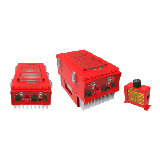
Parts List Table 1-1 Parts List Label Quantity Description PSR-78-9537-XB Wall Mount Bracket Mounting Bracket Template AAI Alarm Cable AC Power Cable Ethernet Cable (Crossover) Anchor Bolt PSR-ANN (Annunciator Panel) Figure 1-1 PSR-78-9537-XB Repeater Parts List Advanced RF Technologies, Inc. -
Page 11: Quick View
Sever CPL (DL Output Donor CPL (UL Output Monitor Port, -30dB) Monitor Port, -30dB) AAI Alarm Port Air Vent Hole ADRF-BBx Battery Port AC Input Port Annunciator Communication / Power Port Heat Sink Figure 1-2 PSR-78-9537-XB Quick View (Bottom) Advanced RF Technologies, Inc. -
Page 12: Figure 1-2 Psr-Ann Annunciator
Audible Alarm Speaker Alarm Indicator Lights Data/Power Port Repeater / Wall Mount Bracket Figure 1-3 PSR-ANN Annunciator Advanced RF Technologies, Inc. -
Page 13: Warnings And Hazards
Also, the donor antenna needs to be mounted outdoors on a permanent structure. WARRANTY Opening or tampering the PSR-78-9537-XB will void all warranties. Lithium Battery: CAUTION. RISK OF EXPLOSION IF BATTERY IS REPLACED BY INCORRECT TYPE. DISPOSE OF USED BATTERIES ACCORDING TO INSTRUCTIONS. - Page 14 Preclude indications that Home/ personal use are prohibited. Use of unauthorized antennas, cables, and/or coupling devices not conforming with ERP/EIRP is prohibited. FCC Part 15.21 Any changes or modifications not expressly approved by the party responsible for compliance could void the user's authority to operate this equipment. FCC Part 15 Class A NOTE: This equipment has been tested and found to comply with the limits for a Class A digital device, pursuant to part 15 of the FCC Rules.
- Page 15 RSS-GEN, Sec. 7.1.2– (transmitters) Under Industry Canada regulations, this radio transmitter may only operate using an antenna of a type and maximum (or lesser) gain approved for the transmitter by Industry Canada. To reduce potential radio interference to other users, the antenna type and its gain should be so chosen that the equivalent isotropically radiated power (e.i.r.p.) is not more than that necessary for successful communication.
- Page 16 ◈LABEL WARNING◈ Part 90 Signal Boosters This is A 90.219 CLASS B DEVICE WARNING. THIS is NOT a CONSUMER device. It is designed for installation by FCC LICENSEES and QUALIFIED INSTALLERS. You MUST have an FCC LICENSE or express consent of an FCC Licensee to operate this device.
-
Page 17: Overview
2. OVERVIEW PSR-78-9537-XB LED indicator lights are located on the inside of the repeater towards the bottom. Below the LED indicators is a button that is used to trigger the door open alarm. Figure 2-1 LED Panel Table 2-1 LED Specifications... -
Page 18: Cable Connection
Figure 2-2 Host/Remote Switch Cable Connection 2.3.1 AC Power AC power is accepted through a standard 3-wire male plug (MS3106A-22-2S) with phase, neutral, and ground leads. The AC power is wired to a high-efficiency DC switching power supply which is UL approved. The AC port is located at the bottom of the repeater and has a free-voltage range input of 100-240V AC. -
Page 19: External Alarm
2.3.2 External Alarm Figure 2-5 External Alarm Port This port should be connected only to the fire alarm control panel. Table 2-2 External Alarm Port Pin Description Bundle ADRF External Alarm Box Alarm Color Pin Description (24 pins) Pin Description Type Black... -
Page 20: Annunciator
2.3.3 RF Figure 2-6 RF Ports The RF connections are made via two 4.3-10 female connectors. The RF connector labeled “DONOR” must be connected to the antenna pointing towards the base station. The DONOR port can receive both 700 and 800MHz public safety signals. -
Page 21: Back Up Battery Port
Battery Backup Port (4-pin Female) If an ADRF-BBS/BBL-24 is connected to the repeater, the battery switch on the PSU must be switched to the ON position. This will enable the repeater to charge the ADRF-BBS/BBL-24 battery backup unit when AC power is present. -
Page 22: Grounding
2.3.6 Grounding The grounding terminal is located at the lower right-hand side of the BDA. A grounding cable should be properly connected before powering on the equipment. Figure 2-10 Ground Cable Terminal Ground terminals located on the side of the repeater and can support a ground cable up to 1.25mm² (16AWG) in diameter and should be permanently connected to a grounding bar. -
Page 23: Alarms
3. ALARMS Message Board Alarms and Notifications Table 3-1 Message Board Alarms and Notifications Parameters Remark AC Fail AC Input is outside of operating range DC Fail DC Output is outside of operating range Temperature The module is above/below the normal operating temperature Current PSU is providing more than the max current System Halt... -
Page 24: External Alarms
External Alarms The PSR-78-9537-XB supports dry contact alarms and can be connected to a fire alarm control panel. The user can program the repeater to either create an open or closed circuit when an alarm is present in the system. -
Page 25: External Alarm Input Interface
Verify that the PSR-78-9537-XB and mounting holes are in good condition Place the PSR-78-9537-XB mounting bracket template up against the wall and mark off mounting holes Drill the appropriate size holes and install the included wall anchors ... -
Page 26: Psr-Ann Annunciator Installation
4.1.2 PSR-ANN Annunciator Installation The PSR-ANN annunciator box has been designed to either mount on top of the PSR-78-9537-XB repeater or can also be wall mounted separately. By default, the mounting bracket is configured to mount to the top of the repeater with the mounting bracket at the bottom of the PSR-ANN annunciator box. -
Page 27: Figure 4-3 Psr-Ann Wall Mount
Figure 4-3 PSR-ANN Wall Mount Advanced RF Technologies, Inc. -
Page 28: Antenna Separation/Isolation
50dB, then isolation of 65dB or greater is required. In the same manner, to utilize the maximum gain of 95dB of the PSR-78-9537-XB, isolation of at least 110dB is required. Advanced RF Technologies, Inc. - Page 29 DO NOT APPLY AC POWER TO THE BDA UNTIL CABLES ARE CONNECTED TO BOTH PORTS OF THE BDA AND THE ANTENNAS. 1. To mount on a wall. Using appropriate screws and anchors attach the BDA to the wall at the four mounting holes.
-
Page 30: Psr-78-9533-X/9537-X Web-Gui Setup
PSR-78-9537-XB WEB-GUI SETUP The Web-GUI allows the user to communicate with the repeater either locally or remotely. To connect to the repeater locally, you will need a laptop with an Ethernet port and an RJ-45 crossover cable. To connect to the repeater remotely, you will need to have an active internet connection via an external modem or LAN. -
Page 31: Status Tab
Status Tab Figure 5-2 Status Tab Advanced RF Technologies, Inc. -
Page 32: Band Info
5.2.1 Band Info The Band Info section displays frequency information along with the corresponding bandwidths that have been set from the Install tab. Input levels for each channel are also displayed in this section. Figure 5-3 Status Tab – Band Info Display 5.2.2 Power &... -
Page 33: Alarms
5.2.3 Alarms This section displays the alarm status for System alarms, RF Alarms, and Power alarms. If an alarm is present in the system, then the color of the alarm tab will change according to the type of failure. Figure 5-5 Status Tab –... -
Page 34: Repeater Info / Repeater Location / Technical Support / Installer Contact Info
Repeater Info: Displays the serial number, latitude, longitude, firmware version, and Web-GUI version Repeater Location: Displays the address where the repeater is installed Technical Support: Displays ADRF’s Technical Support contact information Installer Contact Info: Displays the installer’s name, phone, and e-mail address Advanced RF Technologies, Inc. -
Page 35: Control Tab
Control Tab Figure 5-9 Control Tab Advanced RF Technologies, Inc. -
Page 36: General Settings
5.3.1.1 Emergency Power Off Switch Support The PSR-78-9537-XB now support the ability to connect an extern power switch to turn on/off the high power amplifier via our Alarm Input dry contact pins. This Emergency Power Off (EPO) function is an optional feature that is only active when the function is enabled. -
Page 37: Manual Gain Control
5.3.3 Manual Gain Control Figure 5-13 Control Tab – Manual Gain Control DL/UL Gain: Gain levels of the repeater can be specified here DL/UL ALC Level: Prevents the output power from exceeding the specified value DL/UL Output ALC Offset: If any ALC attenuation has been applied, the system will release this attenuation when the signal level drops by the specified level ... -
Page 38: Install Tab
Install Tab Figure 5-15 Install Tab Advanced RF Technologies, Inc. -
Page 39: Technology
5.4.1 Technology This section allows the user to set the repeater mode to either use PS700, PS800, or PS700+PS800. Figure 5-16 Install Tab – Technology 5.4.2 Band Selection Figure 5-17 Install Tab – Band Selection Band selection allows the user to specify the desired frequencies by inputting the center frequencies and selecting the bandwidths. -
Page 40: Snmp
Channel Center Frequency: The user can input the center frequency of the pass-band. Bandwidth: Allows the user to select the desired bandwidth for the passband. Choices for wideband frequencies include 3, 5, or 10 MHz. Narrowband choices include 6.25, 12.5, 25.0, 75.0 and 200 kHz. The required frequency spacing between channels is 4x the bandwidth from center to center. -
Page 41: Aai Input
5.4.6 AAI Input The PSR-78-9537-XB can accept a dry contact input alarms. The alarm can be labeled in this section. Once the alarm is labeled, it will show up in the system with the new custom names on the Status tab. This feature is only available if the Emergency Power Off switch function is not being utilized. -
Page 42: System
System The System tab allows the user to perform firmware updates, upload closeout packages, view any changes to the system, backup existing configuration, add/remove user accounts, and change the login credentials of the Administrator. 5.5.1 System: Account 5.5.1.1 System: Account – Account Management The Account Management section allows the Administrator to delete any user accounts. -
Page 43: System - Snmp
5.5.2 System – SNMP This section displays The SNMP section allows the user to define the parameters for SNMP v1, v2c, and v3. Community strings for v1/v2c can be specified from here and SNMP user account can be created/deleted from this section. -
Page 44: System - Update
5.5.4 System – Update To perform a firmware update, click on the Update tab and the following screen will appear. Figure 5-29 System: Update Click on the Choose File button and locate the firmware file. Click on the Upgrade button to perform the firmware update. ... -
Page 45: Help
Figure 5-32 Help Logout Clicking the Logout button will log the current user off the system. MAINTENANCE GUIDE FOR PSR-78-9537-XB REPEATER Periodic Inspection Checklist Check for loose connections between the repeater and antennas. If connections are loose, make sure that all connections are tightly fastened properly. -
Page 46: Warranty And Repair Policy
7. WARRANTY AND REPAIR POLICY General Warranty The PSR-78-9537-XB/9537-X carries a Standard Warranty period of two (2) years unless indicated otherwise on the package or in the acknowledgment of the purchase order. Limitations of Warranty Your exclusive remedy for any defective product is limited to the repair or replacement of the defective product. -
Page 47: Specifications
<10us@200KHz BW Power Supply 100 -240 VAC, 60 Hz (Free Voltage) Optional battery backup <150 W / < 222 W Power Consumption (PSR-78-9537-XB / 9537) Max RF Input Power without overdrive -20dBm No damage Max Input Power +10 dBm Impedance 50 Ω... -
Page 48: Mechanical Specifications
Warranty Years 8.5 Description of PSR-78-9537-XB PSR-78-9537-XB/ PSR-78-9537-XB are for Digital Repeater (or BDA) Main devices that PSR-78-9537-XB/ PSR-78-9537-XB includes are Triplexer, DSP, UDC (RF Module), HPA and PSU. For the function of Repeater, see 0 Signal Flow Frequency Information... - Page 49 Specifications Frequency FirstNet + PS 700 758 - 768MHz 788 - 798 MHz Signal Flow Downlink Base Mobile TRIPLEXER TRIPLEXER Station (before DSP) (After DSP) Station Figure 8-1 Downlink Signal Flow 1. Donor Triplexer band Passes DL signal 2. DL UDC (before DSP) amplifies, adjusts this signal received via antenna from Base Station signal to appropriate level and then transmits the signal to DL DSP.
- Page 50 BLOCK DIAGRAM PSR-78-9537 Repeater (4) DSP DL_PATH (1) Donor Antenna (7) Server Antenna (5) HPA Low Noise AMP + Up/Down DL_700 Converter + Drive AMP_DL (DL_700MHz) Low Noise AMP + Up/Down DL_800 Converter + Drive AMP_DL (DL_800MHz) (3) UDC (6) Server Triplexer (2) Donor Triplexer UL_PATH...
- Page 51 Donor/Server Triplexer Specifications Parameter DL_700 UL_700 Insertion Loss Max 1.5dB Max 1.5dB Gain flatness p-p 1dB p-p 1dB Isolation 90dB 90dB VSWR Max. 1.5:1 Max. 1.5:1 Table 0-3 Donor/Server Triplexer specifications DL HPA Parameter Specifications Frequency 758 - 768MHz Rating Gain 35dB1dB Gain flatness p-p 3dB...
-
Page 52: Mechanical Drawing
ALC FUNCTION This Repeater has ALC(Automatic Level Control) function as automatic power down mechanism for protecting system from output overload The picture below is regarding output ALC function Adjustable range of ALC function is minimum 40dB ALC level do not exceed the setting power level Output Input Figure 0-1... -
Page 53: Figure 9-1 Psr-78-9533-X Mechanical Drawing
Figure 8-1 PSR-78-9537-XB Mechanical Drawing Advanced RF Technologies, Inc. -
Page 54: Figure 9-2 Psr-78-9537-Xb Mechanical Drawing
Figure 8-2 PSR-78-9537-XB Mechanical Drawing Advanced RF Technologies, Inc. -
Page 55: Figure 9-3 Psr-Ann Annunciator Mechanical Drawing
Figure 8-3 PSR-ANN Annunciator Mechanical Drawing Advanced RF Technologies, Inc. -
Page 56: Appendix
9. APPENDIX Shutdown Retry Logic The function of the built-in shutdown routine is to protect the repeater from any further damage from a hard- fail that the system may be experiencing. Within 5 seconds of a hard-fail alarm being detected, the repeater will start the shutdown routine. The repeater will shut down by powering off the HPAs (high-powered amplifiers) for 30 seconds.
Need help?
Do you have a question about the PSR-78-9537-XB and is the answer not in the manual?
Questions and answers