Table of Contents
Advertisement
Quick Links
Advertisement
Table of Contents

Related Manuals for Webfleet LINK 640


Summary of Contents for Webfleet LINK 640
- Page 1 LINK 640 Installation Guide 1597779132885 - Draft - 2022-04-29...
-
Page 2: Table Of Contents
Resetting your LINK 640 to factory settings.................. 19 Technical data......................... 20 Addendum......................21 Important Safety Notices and Warnings................. 22 Prohibited uses........................23 CE mark and Radio Equipment Directive for LINK 640............23 FCC information for the user....................23 Specific Absorption Rate (SAR) compliance................25 Triman logo..........................25 Operating temperature......................25 WEEE –... - Page 3 Webfleet Solutions Limited Warranty..............30...
-
Page 4: Installation
Installation... -
Page 5: What's In The Box
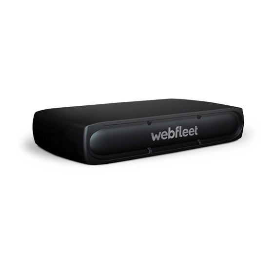
What’s in the box LINK 640 • 1. Yellow LED - connection status indicator. 2. Green LED - system status indicator. 3. Power/CAN connector. 4. Reset button. 5. Service/Update Mini-USB-cable connector. Holder • Power/CAN cable • Fixings - 1 adhesive strip, 4 self-tapping screws and a cleaning tissue... -
Page 6: What You Need For The Installation
A device with internet connection that is able to scan QR codes, has the LINK Toolkit app installed and • the necessary LINK Toolkit login credentials. The QR code of the LINK 640 (on the device label or on the additional QR code label). • All parts contained in the box. -
Page 7: Safety First
Repairs must be carried out by authorised and qualified personnel only. Never replace damaged parts of the unit yourself. Send the defective unit to Webfleet Solutions for repair. Only the qualified staff of Webfleet Solutions are authorised to repair or replace parts. - Page 8 Damage to the device Short-circuits inside the unit can be caused by contact with water or other liquids. The unit may be dam- aged by contact with water. Use and store the unit in an area protected from water.
-
Page 9: Connection Overview
Connection overview 5PE** White NC** Orange/Yellow CAN2L** White CAN2H** Orange/Green CAN1L** White CAN1H** Orange/Blue Brown Brown Vbat* IGN* Black * Make sure this wire is fused with max. 10A. ** Twisted pair. Loose ends of CAN L/CAN H wires must be protected against short circuits. Separate by us- ing a heat shrink tube. -
Page 10: Connecting To The Can Bus
Connecting to the CAN bus Please refer to the Webfleet Solutions tooling for the CAN configuration of your specific vehicle. Tips for the installation For direct connection to the CAN bus select the wire to be as short as possible and needed. Do not wind •... -
Page 11: Connecting To Power
Important: Follow the order of connecting the wires as described below. First connect the wires then insert the plug into the LINK 640. If you have inserted the plug into the LINK 640 first, you must connect the GND wire before you connect the PWR+ wire and the IGN wire as described below. -
Page 12: Choosing The Correct Position
First you need to choose the correct position in which to install your LINK 640. Take the following into consideration: Do not expose the LINK 640 to direct sunlight and/or high temperature for long periods to ensure prop- • er operation. -
Page 13: Mounting The Link 640
You can attach the holder to the top or to the bottom side of the LINK 640. Attaching the holder using the adhesive strip You can use the adhesive strip to fix the LINK 640 to your vehicle. Follow the safety instructions in this document. -
Page 14: Attaching The Holder Using Self-Tapping Screws
5/8 inches) are included in your product package. 1. Choose a flat surface for the LINK 640. Remember, when the LINK 640 is in the holder, it must not be obstructed by metal objects. 2. Insert the screws into the corresponding holes in the holder. -
Page 15: Testing Operation
2. Look at the yellow LED. It should be on and then go off every 3 seconds. As soon as the device has established a connection to WEBFLEET the yellow LED stays on all the time. If the LED keeps flashing for longer than 10 minutes, monitor the LEDs for diagnostics . -
Page 16: Activating The Link 640
In addition to the LINK Toolkit app you can use an online installation tool to activate the LINK 640. To go there please scan the QR code of the LINK 640 that you can find on the device label or on the additional la- bels provided with the device. -
Page 17: Diagnostics
Diagnostics Monitoring operation You can monitor the system operation of your LINK 640 by looking at the green system LED and referring to the table below. Important: The LINK 640 device must be activated in WEBFLEET. GREEN LED mode Unit is in standby mode or is not connected to power. -
Page 18: Support
If for longer than ten minutes, please contact the • Webfleet Solutions support team at www.webfleet.com/ support. Connected. Support If you cannot find the answer to your question with the help of the tables above, please contact the Webfleet Solutions support team at www.webfleet.com/support. -
Page 19: Resetting The Link 640
Restarting your LINK 640 To restart your LINK 640, press the reset button with a thin pointed object until it clicks and keep it pressed down for 1 to 2 seconds. The LINK 640 restarts within approximately five seconds after releasing the but- ton. -
Page 20: Technical Data
To be connected to the ignition clamp of the vehicle to switch on/off the device with the vehicle ignition signal, if available. CAN bus The CAN bus interfaces of the LINK 640 are listen only CAN interfaces. CAN1 H, CAN1 L, High speed/Low speed CAN CAN2 H, CAN2 L, High speed/Low speed CAN 5 PE power supply for external capacitive CAN sensors: For Webfleet Solutions accessories only. -
Page 21: Addendum
Addendum... -
Page 22: Important Safety Notices And Warnings
GLONASS is operated and controlled by the Government of Russia, which is solely responsible for its availability and accuracy. Changes in GPS or GLONASS availability and accuracy, or in environmental con- ditions, may impact the operation of this device. Webfleet Solutions disclaims any liability for the availability and accuracy of GPS or GLONASS. -
Page 23: Prohibited Uses
CE mark and Radio Equipment Directive for LINK 640 This device can be used in all EU Member States. Hereby, Webfleet Solutions declares that the radio equip- ment type telematics black box is in compliance with Directive 2014/53/EU. The full text of the EU decla- ration of conformity is available at the following internet address: https://www.webfleet.com/webfleet/le-... - Page 24 If the user modifies the equipment or its peripher- als in any way, and these modifications are not approved by Webfleet Solutions, the FCC may withdraw the user’s right to operate the equipment. For customers in the USA, the following booklet prepared by the Fed- eral Communications Commission may be of help: "How to Identify and Resolve Radio-TV Interference Prob-...
-
Page 25: Specific Absorption Rate (Sar) Compliance
20cm (8 inches) from your body when the device is transmitting. If you use an accessory not supplied by Webfleet Solutions when you car- ry the device, verify that the accessory does not contain metal and keep the device at least 20cm (8 inches) from your body when the device is transmitting. -
Page 26: How Webfleet Solutions Uses Your Information
The owner of the WEBFLEET contract decides what purposes this information is subsequently used for, who will have access to it, and for how long the information is kept. Please refer to the owner of the WEBFLEET contract for any additional information. This will usually be the owner or lessee of the vehicle. -
Page 27: Model Numbers
Model numbers LINK 640: L0640 Responsible party in North America TT Telematics USA Inc., 100 Summit Drive, Burlington, MA Emmisions information for Canada This device contains licence-exempt transmitter(s)/receiver(s) that comply with Innovation, Science and Eco- nomic Development Canada’s licence-exempt RSS(s). Operation is subject to the following two conditions: This device may not cause interference. -
Page 28: Customer Support Contact (Australia And New Zealand)
To use the LINK 640 you need a valid and active WEBFLEET Telematics Service Platform subscription. Accessories not supplied with this device To access all the features of your LINK 640 one or more of the following accessories are required. LINK CAN Sensor 100 •... -
Page 29: Copyright (C) 2018 - Tcl/Tk - Regents Of The University Of California, Sun Microsystems, Inc., Scriptics Corporation, And Other Parties
Copyright (c) 2018 - Tcl/Tk - Regents of the University of California, Sun Microsystems, Inc., Scriptics Corporation, and other parties https://www.tcl.tk/ This software is copyrighted by the Regents of the University of California, Sun Microsystems, Inc., Scriptics Corporation, and other parties. The following terms apply to all files associated with the software unless ex- plicitly disclaimed in individual files. - Page 30 Webfleet Solutions Limited Warranty...
- Page 31 HOW TO MAKE A WARRANTY CLAIM 3 In order to make a claim of a Defect, you must contact Webfleet Solutions during the Warranty Period via www.webfleet.com to explain the Defect and to obtain an RMA number (Return Materials Authorization) if necessary.
- Page 32 LIMITATION OF LIABILITY 9 Neither Webfleet Solutions nor its suppliers shall be liable to you or to any third party for any damages ei- ther direct, indirect, incidental, consequential or otherwise (including in each case, but not limited to, dam-...
Need help?
Do you have a question about the LINK 640 and is the answer not in the manual?
Questions and answers