Sign In
Upload
Manuals
Brands
ESAB Manuals
Cutter
CROSSBOW
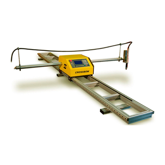
User Manuals: ESAB CROSSBOW CNC Plasma Cutter
Manuals and User Guides for ESAB CROSSBOW CNC Plasma Cutter. We have
1
ESAB CROSSBOW CNC Plasma Cutter manual available for free PDF download: Instruction Manual
ESAB CROSSBOW Instruction Manual (232 pages)
Portable CNC Cutting Machine
Brand:
ESAB
| Category:
Cutter
| Size: 26 MB
Table of Contents
Table of Contents
4
Safety
11
Introduction
11
Safety Hazards and Warnings
11
Electrical Grounding
16
Service Precautions
16
Recommended Safety References
17
International
17
United States
18
Canada
19
Description
21
Machine Overview
21
Machine Components
22
Machine Dimensions
23
Machine Specifications
24
Axis Orientation
25
Installation
27
Receiving Inspection
27
Base Machine Setup
28
Prepare Rail Track
28
Install Central Unit on Rail Track
32
Install Cross Beam Assembly
35
Install Torch Lifter
39
Connect Cables
43
Oxy-Fuel Torch Installation
46
Assemble Torch
46
Install Torch in Torch Holder with Adaptor
47
Connect Torch Hoses
48
Install Gas Supply Hoses
49
Connect Gas Supplies
50
Perform Leak Test
51
Plasma Torch Installation
52
Install Second Cable Holder
52
Install Plasma Torch
53
Install Plasma Interface Cable
54
Install Initial Height Sensing Cable
56
Connect Power and Air to Plasma Unit
57
Initial Power-Up Testing
58
Switching between Metric and Inch
59
Operation
61
Control Panel and Function
61
CNC System Features
62
CNC System Technical Specification
62
Function Keys
62
Input Keys
63
Operational Overview - Oxy-Fuel Cutting
66
Operational Overview - Plasma Cutting
66
Home Screen and Main Menu
67
Main Menu Map
68
Main Menu
68
Auto Mode Menu
69
Manual Mode Menu
70
Edit Mode Menu
71
Auto Mode Screen
72
Speed
72
PROG, PIERCE and KERF
73
Cutting Process Status Indicators
73
Additional Function Key Indicators
73
INPUT and OUTPUT INDICATORS
74
Operating Parameters
74
Machine Coordinate Display
74
Mode / Status Indicators
74
Program Coordinates
74
Graphics Display Area
74
Auto Mode Menu Functions
75
F1】Skipto
75
F2】Manual
75
F3】Resume
75
F4】Preview
75
F5】Kerf
77
F6】More
77
F7】Return
77
Auto Mode more Window
78
Nd Level) Functions
78
F1】OUTLINE Function
78
F2】Wentai
79
F3】ROTATE (Program Rotation)
79
F4】Mirror
80
F5】Scale
80
F6】Nest
81
F7】Tabbing
82
Running a Program in Auto Mode
83
Select the Part Program or Nest
83
Set Cutting Speed
83
Move to Starting Position
83
Start Cutting
83
Arc Voltage Height Control Operation (Plasma Cutting)
83
Functions Available While Running a Program
84
Functions Available During Program Pause
85
Program Pause Screen
85
Key Panel Functions
85
F4】JUMP to (Jump to any Line or Pierce Point)
87
F5】PIERCE# (Go to New Pierce Point)
87
F6】REVERSE (Backward on Path)
88
F7】FORWARD (Forward on Path)
88
Re-Start after Jogging
88
Resuming Parked Programs
90
SKIPTO (Skip to Starting Point)
92
Edge Starting
93
Manual Mode Screen
94
Speed
94
Additional Function Keys and Indicators
95
Manual Mode Menu Functions
96
F1】Auto
96
F2】Step
96
F3】More
96
F4】MACH-0 (Clear Machine Coordinates)
96
F5】RAPID (Rapid Jog Speed)
96
F6】PROG-0 (Clear Program Coordinates)
96
F7】Return
97
Manual Mode more Window
98
Nd Level) Functions
98
F3】REC PT1 And【F4】Rec PT2 (Plate Alignment)
98
F5】COORDS (Set Coordinates)
99
Edit Mode
100
Edit Mode Menu Functions
100
F1】New
100
F2】Load
100
F3】Save
101
F4】Del-File
101
F5】Del-Line
101
F6】Usb
101
F7】Preview
102
USB Access Menu
103
F1】Load
103
F2】Output
104
F3】Select
104
F7】Preview
104
Setup Mode Screen (Parameter Settings)
105
F1】Speed Parameters
106
F2】System Parameters
107
F3】Flame Parameters
108
F4】Plasma Parameters
109
F5】Control Parameters
110
Shape Library
112
Operating Overview - Shape Library
113
Shape Evaluation Screen
114
F1】OD CUT and 【F2】ID CUT
115
F3】Rotate
116
F4】Nest
117
F6】Apply
118
Part Programming Instructions
119
File Format
119
Program Names
119
Program Format
119
Units of Measurement
120
Programming Mode
120
Axis Orientation
120
G-Codes
121
M-Codes
127
Programming Examples
128
Maintenance
133
Routine Maintenance
133
Daily Maintenance
133
Weekly Maintenance
133
Monthly Maintenance
134
Lubrication Points
135
Operating FAQ
136
Basic Troubleshooting
137
Software Service Instructions
141
Boot Menu
141
Backup and Restore Parameters
142
Instructions for Updating Software
143
Changing Machine Name Text
144
Hardware Service Instructions
145
Replacing Main Fuse
145
Removing the CNC
146
Servicing Operator Panel Components
148
Adjusting the Main Power Supply
149
Switching Input Voltage
150
Changing Initial Height Setting
152
Reversing Lift Motor Direction
153
Replacing Arc Voltage Height Control Board
154
Replacing VHC Sensor Board
155
Replacing Motor Driver
156
Removing the Cover
157
Replacing the Main Power Supply
158
Replacing Bearing Blocks
159
Adjusting Rail Axis Drive Pinion Engagement
160
Adjusting Cross Beam Drive Pinion Engagement
161
Adjusting the V-Wheels
162
Replacing Drive Motor
164
Replacing Drive Pinions
165
Replacing V-Wheels
166
Replacing the Solenoid Valve
168
Servicing the Torch Lifter
170
Replacement Parts
173
Introduction
173
Ordering Information
173
Parts List
174
Main Assemblies
174
Central Unit Parts
175
Motion System Parts
176
Internal Electrical Parts
177
Internal Mechanical Parts
178
Internal Drive System Parts
179
Cables and Connectors
180
Torch Station Parts
181
Torch Lifter Parts
182
Plasma Torch Parts
183
Oxy-Fuel Torch Kit
184
Oxy-Fuel Cutting Tips
185
Appendix 1: Programming Code Reference
187
Appendix 2: Error List
189
Appendix 3: Shape Library Variables
191
Shape 1: RECTANGLE
191
Shape 2: CIRCLE
192
Shape 3: L-BRACKET
193
Shape 4: PIE SHAPE
194
Shape 5: TRIANGLE
195
Shape 6: CURVE BKT
196
Shape 7: CHAMFER
197
Shape 8: OVAL
198
Shape 9: RING
199
Shape 10: OCTAGON
200
Shape 11: TAB RECTANGLE
201
Shape 12: CUTOUT
202
Shape 13: LINE CUT
203
Shape 14: ARC SECTOR
204
Shape 15: HOLE CUTOUT
205
Shape 16: RECT. CUTOUT
206
Shape 17: U-SHAPE
207
Shape 18: COM-LINE (Common-Line-Cut Rectangles)
208
Shape 19: TANK BED
209
Shape 20: 4-HOLE FLANGE
210
Shape 21: 6-HOLE FLANGE
211
Shape 22: IMPELLER
212
Shape 23: 2-HOLE FLANGE
213
Shape 24: WES TEST
214
Appendix 4: Oxy-Fuel Cutting Parameters
215
Cutting Data for Oxweld C-69 Torch
215
Cutting Data for Oxweld C-70 Torch
215
Appendix 5: PT-37 Plasma Cutting Parameters
217
Mild Steel Cutting
217
Aluminum Cutting
218
Stainless Steel Cutting
219
Appendix 6: Wiring Diagrams
221
Advertisement
Advertisement
Related Products
ESAB OXWELD C-60
ESAB OXWELD C-60-S
ESAB CIGWELD COMET
ESAB Cro
ESAB Cutmaster 80
ESAB ESABMig C420s
ESAB COOL 2
ESAB Caddy 200
ESAB Caddy TA33
ESAB Caddy 130
ESAB Categories
Welding System
Welding Accessories
Cutter
Control Panel
Flashlight
More ESAB Manuals
Login
Sign In
OR
Sign in with Facebook
Sign in with Google
Upload manual
Upload from disk
Upload from URL