Page 1
CAUTION! PLEASE KEEP POWER SWITCH ON BEFORE OPERATING THIS EQUIPMENT Turbo Air Speed up the Pace of Innovation Underbar Equipment Back Bars Installation and Operation Manual Please read this manual completely before attempting to install or operate this equipment!
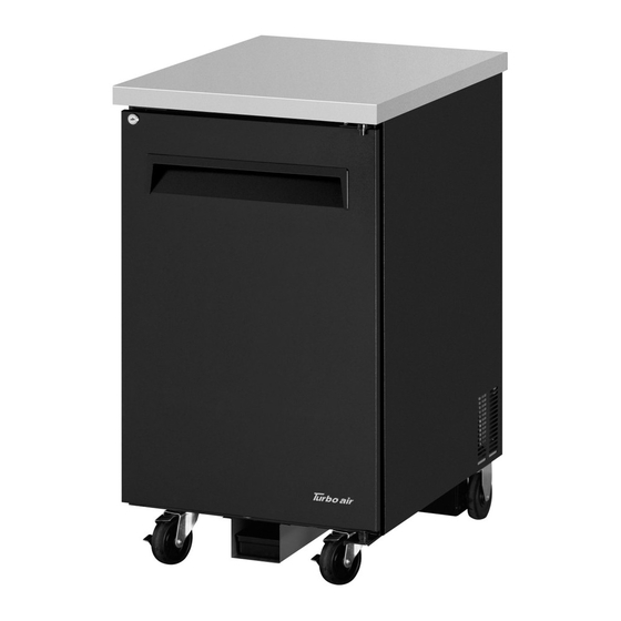
 TBB-1SB...
CONTENTS PAGE SPECIFICATION SERIAL NUMBER INSTALLATION OF THE CASTERS Draft Arms Towers Installation Schematic Diagram Beer Line & CO Line Installation Schematic Diagram Caution "IMPORTANT" INSTALLATION CLEANING BASIC OPERATION BEFORE REQUESTING SERVICE WARRANTY 11-12 SPECIFICATIONS MODEL COMPH.P. V/Hz REFRIGERANT AMPS WEIGHT TBB-SB 1/10...
INSTALLATION OF THE CASTERS According to model, refer to the assembly position of casters. TCB-2SD, TBD-2SD, TBB-2SB, TBB-2SG TCB-3SD, TBD-3SD, TBB-3SB, TBB-3SG TCB-4SD, TBD-4SD, TBB-4SB, TBB-4SG This picture is a plan view of bottom cabinets. CB is an abbreviation of the caster with a brake. Other casters don't have a brake.
BEER LINE & CO LINE Installation Schematic Diagram Distributor Fixture Line Beer Line#1 Beer Line#2 Beer #1 Beer #2 TCB-2SD, TCB-3SD, TCB-4SD TBD-2SD, TBD-3SD, TBD-4SD TBD-2SB, TBD-3SB, TBD-4SB * Assemble BEER LINE & CO LINE as above drawing.
CAUTION "IMPORTANT" DIRECT DRAW On direct-draw dispensers the drain is located at the front of the cabinet. To plumb in the drain, connect 5/8” P.V.C. pipe to the 5/8” barbed fitting supplies with the unit. * Don't pull out or Turn drain line.
Page 6
CAUTION "IMPORTANT" TBB-2SG, TBB-3SG, TBB-4SG A. Excessively opening the door will cause the breakdown. B. Handle with care as shutting the door. 1. POWER CORD - Be sure the power cord is connected to the proper voltage, and amps should be run before connecting power cord to outlet. - A protected circuit of the correct voltage and amperage must be run for connection of the line cord.
1. GOOD AIR CIRCULATION - Do not place any object that will restrict air flow in front or back grills. - Turbo air highly recommends that there is ample space in rear of unit. 3 inches or more is best.
CLEANING Before cleaning, unplug the unit. 1. CLEANING THE INTERIOR AND EXTERIOR - The interior and exterior of the unit can be cleaned using warm water with soap. - Do not use an abrasive cleaner because it will scratch the surface. 2.
BASIC OPERATION REFRIGERATORS 1. The controller(thermostat) is located at the back right inside of the unit. 2. The factory setting maintains about 38˚F(3˚C) inside. 3. Set toward “counter clock wise” warmer temperature and “clock wise” for colder temperature. Temperature Controller (Thermostat) 4.
BEFORE REQUESTING SERVICE SYMPTOMS CAUSES SOLUTIONS Cooler is freezing • Thermostat set too cold. • Turn the temperature dial to a products warmer setting. The unit does not • There is a power connection • Check the power cord to make refrigerate at all.
Page 11
TWO YEAR WARRANTY Turbo air warrants to the original purchaser of every new Turbo air refrigerated unit, the cabinet and all parts thereof, to be free from defects in material or workmanship, under normal use and service, for a period of two (2) year from the date of original installation or 27 months after shipment date from Turbo air , whichever occurs first.
Page 12
3. ALTERATION, NEGLECT, ABUSE, MISUSE, ACCIDENT, DAMAGE DURING TRANSIT OR INSTALLATION, FIRE, FLOOD, ACTS OF GOD. TURBO AIR is not responsible for the repair or replacement of any parts that Turbo Air determines have been subjected after the date of manufacture to alteration, neglect, abuse, misuse, accident, damage during transit or installation, fire, flood, or an Act of God.
(2) year from the date of original installation or 27 months after shipment date from Turbo Air, whichever occurs first. Any part, covered under this warranty, that are by Turbo Air to have been defective within two (2) year of original installation or twenty seven (27) months after shipment date from manufacturer, whichever occurs first, is limited to the repair or replacement, including labor charges, of defective parts or assemblies.