
Subscribe to Our Youtube Channel
Related Manuals for Bilanciai FLYNET 100


Summary of Contents for Bilanciai FLYNET 100
- Page 1 WEIGHING INDICATOR FLYNET 100 USE, MAINTENANCE AND INSTALLATION MANUAL Edition 30/06/2021 Manual code 81320615...
-
Page 3: Table Of Contents
FLYNET 100 CONTENTS INTRODUCTION ..............................4 ................................4 OREWORD ..............................5 OCUMENTATION ................................. 5 YMBOLS ............................6 LOSSARY OF TERMS USED ........................... 8 ESCRIPTION OF THE INDICATOR ..................................8 ......................9 ECHNICAL CHARACTERISTICS OF THE INDICATOR ..........................10 ECLARATION OF CONFORMITY ...................... - Page 4 FLYNET 100 5.2.1.1.2 Serial Scale ..............................42 5.2.1.1.3 Network scale ..............................44 5.2.1.1.4 Sum Scale ..............................46 5.2.1.1.5 Configurable Sum Scale ..........................48 5.2.1.2 Stamping management.............................53 5.2.1.3 Metrological information..........................53 5.2.1.4 System Information ............................54 5.2.1.5 Display Configuration ............................54 5.2.1.6 Metrological Events Log............................54 5.2.1.7 Scale Diagnostics Configuration ........................55 5.2.1.8...
- Page 5 FLYNET 100 6.2.3 Pulse input analogue output board ......................96 ERROR MESSAGES ............................97 ..............................97 NDICATOR ERRORS ................................ 97 CALE RRORS PARAMETER CUSTOMISATION .........................99 ACCESS TO METROLOGICAL PARAMETERS ..................... 100 ........................... 100 ERSION WITH CONNECTORS ..........................101 ERSION WITH CABLE GLANDS ............................
-
Page 6: Introduction
FLYNET 100 INTRODUCTION Foreword • The purpose of this manual is to inform the operator on the basic requirements and criteria for installation, correct and safe use of the weighing equipment and execution of a systematic maintenance through texts and figures •... -
Page 7: Documentation
FLYNET 100 Documentation The standard documentation supplied with the FLYNET 100 indicator consists of: • QUICK START This is a multilingual document, printed on paper, which contains brief instructions for immediate use, as well as the declaration of conformity and the main danger warnings. -
Page 8: Glossary Of Terms Used
FLYNET 100 Glossary of terms used The manual uses technical terminology or terminology with different meaning from the common one. The terms and abbreviations that may be used in the documentation provided are explained below. DANGER: a potential source of injury or damage to health;... - Page 9 FLYNET 100 WEIGH/PRICE LABELLER: Automatic catchweigher that labels individual articles with the weight value, and price information. O.I.M.L. – International Organization of Legal Metrology OIML RXX requirement Where XX is used to specify the requirement according to the category of measuring instruments OIML R76-1 and OIML R76-2: (NAWI) Non-automatic weighing instruments.
-
Page 10: Description Of The Indicator
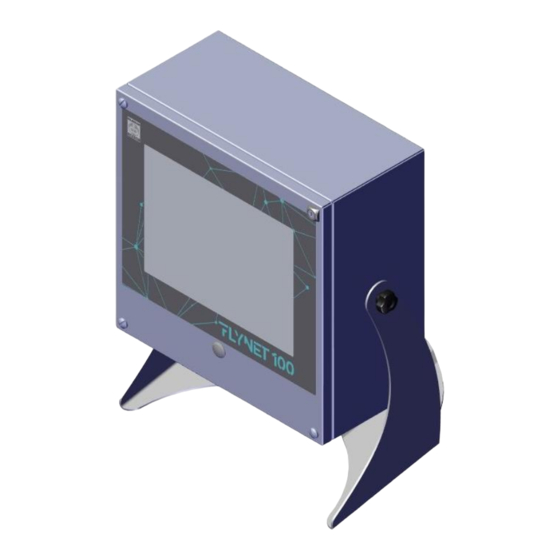
FLYNET 100 Description of the indicator The FLYNET 100 indicator allows performing highly accurate and reliable weighing operations. • Designed for industrial applications. • Supplied as standard with metrological weighing management software. • Body in ABS and stainless steel; available both in tabletop and wall mounting version. -
Page 11: Technical Characteristics Of The Indicator
FLYNET 100 Technical characteristics of the indicator Power supply Direct 12 Vdc/3 A (Min 11 V - Max 15 V) Via network adapter L+N+R 110 - 240 Vac (-15% ... +10%) 1.8 A 50 - 60 Hz 60W Max Ground socket... -
Page 12: Declaration Of Conformity
FLYNET 100 Communication ports USB Type A 4 (+1 internal) Serial ports 2 x RS232 (COM4 /COM6) 1xRS232 + 1xRS422 (COM4/COM7) 2xRS232 + 1xRS422 (with optional bifid cable) 1xRS232 (COM8 option) 1xRS232/RS422 (COM9 option) Ethernet 10/100 Inputs - Outputs Expansions... -
Page 13: Indicator Overall Dimensions And Weight
FLYNET 100 Indicator overall dimensions and weight 1.9.1 Tabletop IC stainless steel version Figure 1.9-1 - Weighing indicator dimensions, tabletop IC stainless steel version • Dimensions (in mm): see Figure 1.9-1. • Weight: 5 kg 1.9.2 Wall-mounted I stainless steel version Figure 1.9-2 - Weighing indicator dimensions, wall-mounted stainless steel version... -
Page 14: Instructions For Disposal Of Electrical Or Electronic Waste
FLYNET 100 1.10 Instructions for disposal of electrical or electronic waste This symbol on the weighing instrument purchased indicates that: • This electrical or electronic equipment cannot be disposed of as solid urban waste. • Separate collection is required. •... -
Page 15: Warranty
FLYNET 100 • exact address of the site/factory where the equipment is installed • contact person. 1.12 Warranty In the construction of the equipment/indicator, the manufacturer has used materials whose type and quality are considered to be suitable in its unquestionable judgement. -
Page 16: Spare Parts
MOTHERBOARD-DIADE SERIES ANALOGUE/DIGITAL CONVERTER 47180119 1.13-1 CONNECTION 47180129 MOTHERBOARD-DIADE SERIES DIGITAL CELL INTERFACE CONNECTION 1.13-1 47501016 MOTHERBOARD-FLYNET 100 SERIAL DRIVER BOARD CONNECTION 1.13-1 MOTHERBOARD-FLYNET 100 SCALE 3 AND 4 ANALOGUE/DIGITAL 47501017 1.13-1 CONVERTERS CONNECTION 52050025 SWITCHING POWER SUPPLY UNIT 100-240VAC/12VDC 1.13-1... - Page 17 FLYNET 100 Figure 1.13-1 - Stainless steel indicator spare parts...
-
Page 18: Safety Requirements
FLYNET 100 SAFETY REQUIREMENTS Not allowed uses The equipment purchased is a metrological instrument intended for non-automatic weighing and as such has been designed and manufactured. The primary use for which it is intended is the weighing of goods. •... -
Page 19: Delivery And Installation
FLYNET 100 DELIVERY AND INSTALLATION COM9 COM8 Figure 3-1 - Indicator bottom with connectors Key: 1. Slots for optional boards 2. Scale 1 3. Scale 2 4. Scale 3 5. Scale 4 6. HDMI port (optional) 7. I/O port 8. COM4 port 9. - Page 20 FLYNET 100 Figure 3-2 - Indicator bottom with cable glands Key: 1. Slots for optional boards 2. Scale 1 3. Scale 2 4. Scale 3 5. Scale 4 6. I/O port 7. COM4 port 8. COM6/ 7 port 9. Ethernet port 10/100 Mb/s 10.
-
Page 21: Installation
FLYNET 100 Installation ATTENTION This indicator must be installed indoors, protected from the weather, as it is not designed to withstand the elements. 3.1.1 Tabletop installation Place the indicator on a fixed surface (table or desk without wheels) so that the monitor is not hit by direct light to avoid reflections, making sure that it is stable and well supported on the non-slip feet. -
Page 22: Wiring Diagram (Version With Connectors)
FLYNET 100 3.2.2 Wiring diagram (version with connectors) For the correct connection of the indicator to the mains, proceed as follows: • Connect the indicator to the power supply unit; • Connect the power supply unit to the correct socket using the proper cable. -
Page 23: Wiring Diagram (Version With Cable Glands)
FLYNET 100 WARNING The sizing and laying of the power cable and the external disconnect switch are the responsibility of the customer. 3.2.3 Wiring diagram (version with cable glands) Connection to the power supply line is the responsibility of the installer. The customer must install the protective conductor and the power supply cable through specialised personnel. - Page 24 FLYNET 100 DANGER Check that: • The power supply line of the indicator has voltage and frequency as indicated on the stamped plate on the indicator bottom; • The socket to which the indicator is connected is provided with grounding pin;...
-
Page 25: Connecting The Indicator To The Weighing Platform
FLYNET 100 Connecting the indicator to the weighing platform For the connection of the indicator to the weighing platform, a pre-wired cable is normally supplied whose female connector must be fully inserted into the 9/15 pin male connector (JBIL) located at the bottom of the indicator. -
Page 26: Wiring Diagram (With Platform)
FLYNET 100 3.3.1 Wiring diagram (with platform) Figure 3.3-1 - Connecting the indicator to the scale Key: 1. Weight display indicator. 2. Weighing platform or weighbridge. 3. Scale cable with 9/15 pin connector. 4. Scale input. 5. Equipotential cable with eyelet wire terminals. -
Page 27: Digital Scale Serial Connection
FLYNET 100 3.3.3 Digital Scale serial connection 15-pin female D-sub connector. DESCRIPTION 485- EX + EX + EX - EX - 485+ EX - NC = Reserved do not connect The connection to the digital cells is made with serial transmission type RS485 using a shielded 6- conductor cable. -
Page 28: Serial Connections
FLYNET 100 Serial connections 3.4.1 COM4 serial connection 9-pin female D-sub connector. DESCRIPTION RX232 TX232 NC = Reserved do not connect 3.4.2 COM6/7 serial connection (option) 9-pin female D-sub connector. DESCRIPTION RX422 - RX 232 TX 232 RX422 + TX422 -... -
Page 29: Com8/9 Serial Connection (Option)
FLYNET 100 3.4.3 COM8/9 serial connection (option) 9-pin female D-sub connector. DESCRIPTION RX422 - RX 232 TX 232 RX422 + TX422 - TERMINATOR TX422 + NC = Reserved do not connect WARNING On this D-sub connector there are two complete serial ports COM8 RS232 and COM9 RS232/RS422. -
Page 30: Input/Output Connection
FLYNET 100 Input/Output connection Input/output contacts are available on the JI/O terminal board at the rear of the indicator Figure 3.5.1 – Terminal board pinout Figure 3.5.2 - JI/O terminal board connection diagram for Input/Output connection... -
Page 31: Input Connection
FLYNET 100 3.5.1 Input connection ATTENTION Electrical characteristics Input: maximum voltage ≤ 5 Vdc maximum current ≤ 5 mA The inputs can be controlled through dry contacts or through NPN transistors (common negative). 3.5.2 Output connection ATTENTION Electrical characteristics Output: switching voltage ≤ 24 V (AC/DC) switching current ≤... -
Page 32: Controls, Switching On And Off
FLYNET 100 CONTROLS, SWITCHING ON AND OFF On/Off key To switch on the correctly powered indicator (connected to the mains through the power supply unit), press the key on the front part. Figure 4.1-1 – Switching on A progress bar on the display with messages indicates the start phase. - Page 33 FLYNET 100 Figure 4.1-2 - Green LED on the power supply unit To switch the system completely off, pull the plug out of the power outlet...
-
Page 34: Touch Screen
FLYNET 100 Touch screen The commands are sent to the indicator via the TOUCH SCREEN. External keyboard and mouse It is possible to connect a mouse and keyboard to the USB ports as control devices. The indicator recognizes common USB mouses and USB keyboards with plug & play system. -
Page 35: Using The Indicator
FLYNET 100 USING THE INDICATOR Refer to the application manual and parameter manual. Indicator configuration It allows setting the parameters for hardware components and system services. These parameters are divided into functional groups. To access each group, simply press on the desired icon. -
Page 36: System
FLYNET 100 System Metrology Stamping, metrology information, parameters and scale management sampling Serial ports COM configuration (serial ports) Printers / Readers / Axis management (when service active), System memory, Inputs Outputs setting printers, readers, inputs and outputs Error notification /... -
Page 37: Internal Scale
FLYNET 100 5.2.1.1.1 Internal Scale The internal scale is a Scale that uses the converter on board the indicator. The type of scale is determined by the type of converter installed. When the internal scale is created, the programme checks the type of converter. - Page 38 FLYNET 100 Any tares set or acquired are automatically deleted when the scale returns to zero, i.e. gross weight = 0 Any tares set or acquired remain stored even when the scale has no load and therefore the gross weight = 0...
- Page 39 FLYNET 100 Divisions may vary while the weight stable signal is maintained. On indicators subject to metrical verification, this parameter must be set to 0 (zero) or 1. Stability Signal Very fast (5 Speed at which the stable weight signal is displayed.
- Page 40 FLYNET 100 • 1: the indicator has a single weighing range for the entire range of the scale capacity. • 2MD: the indicator has two weighing ranges with MULTI- DIVISION mode • 2ME: the indicator has two weighing ranges with MULTI- EXTENSION mode •...
- Page 41 FLYNET 100 SAMPLING PROCEDURES Zero Only Zero sampling is necessary when the scale has already been calibrated and the zero value has moved when the unit switches on. This can happen when the preset tare is not known exactly at the moment of the first sampling, or when an unexpected weight is on the scale.
- Page 42 FLYNET 100 1 PT sampling the full scale value. Removing the weights in inverse order samples the descent. The sampling procedure is the same as that used by the full scale zero system, but in this case several points must be sampled.
- Page 43 FLYNET 100 the indicator shows a message of incorrect angle calibration. Replacing Procedure to replace one cell inside the plant. the cell When a cell is replaced within a system consisting of more than one digital cell, the indicator detects the change and displays an error (-07-). This error can be corrected using the cell replacement procedure.
-
Page 44: Serial Scale
FLYNET 100 PROTECTION The created scale management page contains a protection option. Select “PROTECTION” to activate an additional software protection to control access in the scale management page. To temporarily remove the protection, use your annual password. 5.2.1.1.2 Serial Scale The serial scale (serial weight repeater) is a scale not present on board the indicator. - Page 45 FLYNET 100 Repeater scale connection port Number of the Set the number of the indicator from indicator to be which the weight is requested queried Number Set the number of the indicator on which repeater you are working, i.e. the weight repeater...
-
Page 46: Network Scale
FLYNET 100 Tare value Indicate whether the tare must be maintenance maintained also for subsequent weighing operations Repeater scale connection port Sartorius Capacity Indicate the maximum capacity of the Scale Division Indicate the division used for the Scale Unit Indicate the unit of measurement used by... - Page 47 FLYNET 100 To create a network scale click on the “ADD” button on the scale display page. It is possible to have up to 2 internal scales and 4 total scales (e.g. 2 in the network and 2 internal or...
-
Page 48: Sum Scale
FLYNET 100 5.2.1.1.4 Sum Scale The sum scale allows creating a scale where the weight is given by the sum of the weighing platforms indicated. To create a sum scale, press “ADD”, select “standard sum scale” and select which scales you want to sum up. - Page 49 FLYNET 100 The higher the number, the greater the filtering. SUM PARAMETERS A, B, C... Indicates which of the scales present are used to create the sum scale...
-
Page 50: Configurable Sum Scale
FLYNET 100 5.2.1.1.5 Configurable Sum Scale In the "Configurable sum scale" version, the sum result is processed as an additional scale with its own characteristics (capacity, division, zero management, tare management, etc.). To create a configurable sum scale, press "ADD", select the configurable sum scale and confirm. - Page 51 FLYNET 100 TARE Tare Device Activated It is possible both to set the tare through acquisition of the weight on the scale or by entering a tare value directly from the keyboard Self-weighing only It is only possible to set the tare through acquisition of the weight on the scale;...
- Page 52 FLYNET 100 ZERO Forced zero Defines the range around zero within which forced zero setting will be performed on scale unloading or in the presence of a 0.25 weight stable signal. "Scale unloading" refers to the moment when the weight falls below the minimum weighing value. On indicators subject to metrical verification, this parameter must be set to 0 (zero).
- Page 53 FLYNET 100 STABILITY Number of Allows setting the number of divisions by which the weight may Stability vary while the weight stable signal is maintained. On indicators Divisions subject to metrical verification, this parameter must be set to 0 (zero) or 1.
- Page 54 FLYNET 100 FIELDS Fields Defines the number of weighing ranges into which the nominal capacity of the instrument is divided. It is possible to select: • 1: the indicator has a single weighing range for the entire range of the scale capacity.
-
Page 55: Stamping Management
FLYNET 100 5.2.1.2 Stamping management Allows you to set the standard and the type of stamping. STANDARDS Not Legal It allows deciding whether the scale is to be used for legal purposes (e.g. commercial transactions with verification by the component metrology inspector), or for internal purposes. -
Page 56: System Information
FLYNET 100 5.2.1.4 System Information IP address IP address of the indicator Software Programme code and release Patch Patch code for BSP (if any) BSP code, release and date and GPIO release Physical address of the indicator 5.2.1.5 Display Configuration Gross weight This parameter allows setting the Letter "B"... -
Page 57: Scale Diagnostics Configuration
FLYNET 100 5.2.1.7 Scale Diagnostics Configuration Scale Statistics It records the number of times the weight loaded on the scale exceeds the minimum weighing value. It is possible to view the data from Scale Diagnostics Log, and a file is also generated in the system/statistics folder that replicates the same data. -
Page 58: Scale Diagnostics Log
FLYNET 100 5.2.1.8 Scale Diagnostics Log The scales on which the statistical survey is active are displayed. Year Editable field to select the reference year of the statistics to be displayed Total Number Of Number of times the weight loaded on the scale exceeds the minimum... -
Page 59: Serial Ports
FLYNET 100 5.2.2 Serial Ports From this page it is possible to set the serial transmission parameters of the COM ports. The COM ports that are always physically present are: COM4, COM6 and COM7. If an optional serial expansion board is installed the COM ports are: COM8 and COM9. - Page 60 FLYNET 100 signal must be activated. Memory full Set the percentage at which the memory is considered full. Memory check time Allows setting the check interval. Displays alarm Enables the display of messages. messages Inputs 2 internal inputs and, if an optional board is installed inside the Flynet Inputs / indicator, it is possible to view the additional inputs available.
- Page 61 FLYNET 100 • Weight ≥ setpoint Timeout Time, expressed in seconds, after which the output is activated Threshold Editable field to enter the weight value. The system uses the unit of measurement adopted by the scale. Type of weight It is possible select the type of weight to activate the output.
-
Page 62: System Memory
FLYNET 100 without interpreting them) Then select a COM port to which the reader will be connected. 5.2.3.1 System Memory Service that checks the internal memory use and signals when the set limits are exceeded. Memory almost full Set at what percentage the memory almost full signal must be activated. -
Page 63: Log Management And System Errors
FLYNET 100 5.2.4 Log Management and System Errors 5.2.4.1 Error notification Allows managing the Managed Framework Log generated by the device. GENERAL Log level per file Allows choosing the kind of errors to store. TRACE Additional information log for service... -
Page 64: Access Levels
FLYNET 100 5.2.5 Access levels The use of access passwords allows limiting the setting and/or deletion of sensitive data by unauthorised personnel. To activate them press the enable button next to the access level wording. Then define the initial access level. -
Page 65: Buzzer
FLYNET 100 5.2.6 Buzzer There is a buzzer inside the Flynet indicator that triggers when an icon is selected. Enable buzzer Enable buzzer every time you press the screen Disable buzzer 5.2.7 Date and time The Flynet indicator contains a calendar clock kept active by the buffer battery installed on the motherboard. -
Page 66: Changing The Date
FLYNET 100 5.2.7.1 Changing the date: next month previous month selection of the day date confirmation 5.2.7.2 Changing the time: increases minutes increases time summer time decreases minutes decreases time confirms time 5.2.7.3 Synchronise with the Internet: No dedicated page is displayed, the function immediately synchronises the internal clock with an internet server, there are no subsequent synchronisations, the function is one-shot and is activated only when requested with the key. -
Page 67: Email
FLYNET 100 The servers that are reached during Internet synchronisation are the following: IP ADDRESS SERVER “206,189,118,143” ntp.coreblock.io “37.247.53.178” nettuno.ntp.irh.it “195.13.23.5" ntp1.belbone.be “195.13.1.153” ntp2.belbone.be “131.188.3.220” ntp0.fau.de “131.188.3.220” ntp1.fau.de The first server to respond will also perform the synchronisation. 5.2.8 Email The email service is configured in this menu. -
Page 68: Cards
The "CB" coding is used in the badge cards supplied by card Cooperativa Bilanciai; these cards are composed in such a way as to have an initial check digit which allows the master indicator to prevent the weighing to all badges which do not have an initial check digit equal to that established during the card initialisation phase. -
Page 69: Pdf And Network Printer
The activated services are linked to the indicator, they are not lost in case of indicator software update. If Core is replaced, it is necessary to reactivate the services; contact the Cooperativa Bilanciai for information on the procedures 5.4.1 Network printer This feature allows the indicator to use a network printer as indicator main or secondary printer. - Page 70 FLYNET 100 The parameters to be set are: IP address Set the IP address of the printer you want to use Port Enter the printer communication port address (9100 standard) Type of printer Select a driver from the list according to the printer used: •...
-
Page 71: Pdf
FLYNET 100 5.4.2 This function allows the indicator to create an electronic PDF file. To use this function, proceed as follows: • Check that the service is active, otherwise it is not possible to create a PDF file • Go to the PDF-Network Printer section •... - Page 72 FLYNET 100 server Password Provide password to access the server Port Specify the communication port to the server Press Test to check that the Flynet indicator (client) is able to connect with the FTP server; if the message 'Test OK' is displayed, press Save and Exit to confirm the configuration and exit the settings page.
-
Page 73: Transmission
FLYNET 100 Transmission The indicator is equipped with external serial and Ethernet communication ports. It is therefore possible to interface and communicate with various external devices such as displays, weight repeaters, PCs, PLCs and so on. The data that can be transmitted are linked to the indicator internal programme and therefore cannot be changed. - Page 74 FLYNET 100 Refer to the following settings to configure the Mpp transmission: Weighing request From key From serial Data transmission At the end of the operation From serial Save tare Enabled or disabled Type of reply Standard Std EN45501:2015 Date and time + indicator number...
-
Page 75: Network
FLYNET 100 5.5.2 Network This function allows creating an external transmission using the network board on the Flynet indicator. The indicator IP address, subnet mask, default gateway and DNS settings can be found in the Start menu, refer to the relevant manual to configure them. -
Page 76: Serial
FLYNET 100 or by activating a weighing input; the indicator then behaves as follows: sends the data 3 times consecutively, if the indicator receives the ACK character (06H) it waits for a new request; If it receives the NAK character (15H) it retransmits the string because the previous transmission failed;... -
Page 77: Indicator Parameters
FLYNET 100 SASCO1 The following protocols are available: On request, Remote commands telecontr- The following protocols are available: Cyclic, On Demand, extended ACK NAK, Remote Commands Protocol Cyclic, i.e. the string is transmitted continuously immediately after the indicator is correctly switched on, the cyclic string uses the transmission interval to time the data output On request, i.e. -
Page 78: Field Bus
FLYNET 100 5.5.5 Field bus 5.5.5.1 Profibus It is possible to connect a Profibus gateway to the indicator that can interface with an external PLC system. Visit the manufacturer's website to check the gateway characteristics. The field bus transmission configuration parameters are as follows:... -
Page 79: Modbus-Rtu
FLYNET 100 Waiting for stable Enabled/disabled (for SASCO1 string only) weight Stable weight Stable weight waiting time for data string sending (valid for SASCO1 string time out (ms) only) Once the transmission on the field bus has been configured it is possible, by clicking on the TEST button, to enter the section of writing and reading tests. - Page 80 FLYNET 100 Input Register (Op.code = 04) (Read-only) Variable Type Register Notes Scale Gross weight Float Net weight Float Tare Float Max capacity Float Division Float 9-10 Gross weight (high resolution) Float 11-12 Only if non-legal indicator Net weight (high resolution)
- Page 81 FLYNET 100 Optional outputs Read write 1201...12xx Slot2 Discrete input (Op.code = 02) (Read-only) Variable Type Register Notes Input/Output Input 01 Read-only 1001 Input 02 Read-only 1002 Optional inputs Read-only 1101...11xx Slot1 Optional inputs Read-only 1201...12xx Slot2 The addresses in the table are all in Base 1.
-
Page 82: Printed Data String
FLYNET 100 5.5.6 Printed data string Through the printed data string it is possible to send to a PC a string containing different data such as weight, indicator IP address, operation type and so on. The composition of the printed data string varies depending on the programme installed on the indicator. -
Page 83: Transmission Of Printed Data String Via Serial Transmission
FLYNET 100 Separator Point Checksum Enabled/disabled Enabled Enabled/disabled 5.5.6.2 Transmission of printed data string via serial transmission The parameters available for serial transmission are as follows: Port The COM ports available are those indicated in the drop-down menu, select one of the... -
Page 84: General
FLYNET 100 Separator Point Checksu Enabled/disabled Enabled Enabled/disabled 5.5.6.3 General From this page it is possible to choose whether or not to transmit the first weighing, this parameter is enabled for example in double weighing operation. Transmit first Yes/No weighing operation 5.5.6.4 Delete data... -
Page 85: Themes
FLYNET 100 The services available are: Permanent weight memory, used in legal weighing. When the system is approved and legal weighing is enabled, the system automatically generates the MPP code and enters the data into the MPP archive. Enabling the service therefore allows enabling the display of data and remote controls. -
Page 86: Shortcut Keys
FLYNET 100 Shortcut keys The tools menu allows customising the shortcut keys. Click on the relevant icon to access the customisation page. When the application is installed, some default shortcut keys are already present. They refer to the specific functions of the software, so they may vary. The 4 shortcut keys in the first line will be positioned in the shortcut line above the metrology weighing keys. -
Page 87: Error Management
FLYNET 100 5.11 Error management In this menu it is possible to manage the errors displayed concerning Scale and Printer. Depending on the category chosen, the error will be displayed in different ways: Category Effect The error is displayed inside the status bar at the top of the screen The error is displayed in a pop-up window in the centre of the screen. -
Page 88: Database
FLYNET 100 5.12.1 Database In the Others section of the Application/Others menu it is possible to configure the database management. Click the 'Database’ icon to access the configuration: Connection Local Remote Local: Database \Nand_flash\Public\Managed The database is saved directly on the indicator in... -
Page 89: Adding An External Printer
FLYNET 100 5.13 Adding an external printer To connect a printer to the indicator, simply follow this procedure: 1. Navigate to the 'Printers / Readers / IOs’ menu, to reach it follow the path Menu / Tools / Configuration / System;... -
Page 90: Adding A Reader
FLYNET 100 5.14 Adding a reader To connect a Flynet indicator reader, simply follow this procedure: Navigate to the 'Printers / Readers / IOs’ menu, to reach it follow the path Menu / Tools / Configuration / System; Select Readers tag;... - Page 91 FLYNET 100 Activate the service from the ‘Activating utilities’ page, to activate it refer to paragraph 5.6 on page 77; Once the service is activated, enter the configuration menu and select 'PDF-Network printer'; Depending on the activated option, select network or PDF printer;...
-
Page 92: Testing A Serial Transmission
FLYNET 100 5.16 Testing a serial transmission The indicator is able to send a data string to external devices. The available data strings are listed in paragraph 5 on page 30. Once the transmission has been configured, whether serial or network, it can be tested via PC. Then connect the free end of the cable to the PC, using an adapter if necessary, and open a software capable of handling incoming data traffic (example: Hyper Terminal). -
Page 93: Options
FLYNET 100 OPTIONS The FLYNET 100 weighing indicator provides for the installation of optional boards, peripherals and accessory software. Some options also include the firmware update. Contact the After-Sales Service or the Sales Service Network. The options currently provided (at the date of writing of this manual) are: •... -
Page 94: Optional Board Overview
FLYNET 100 Optional Board Overview 6.2.1 Sound board Figure 6.2-1 - Sound board The sound board consists of: • Lower microphone input jack • Upper headphone output jack, • Amplified loudspeaker output top clamp Clamp numbering from below (pin1 at the bottom): •... -
Page 95: In/12 Out Board
FLYNET 100 6.2.2 8 in/12 out board Function description The 8 input/12 output expansion board allows the weighing indicator on which it is installed to manage 8 dry contact input signals (coming for example from a relay output) and to provide 12 digital dry contact output signals. - Page 96 FLYNET 100 Inputs Maximum voltage (DC) +24 V Maximum current (DC) 40 mA Notes Inputs can be controlled by dry contact outputs (e.g. relays) or NPN NO transistor outputs Outputs Maximum switching voltage (AC/ DC) Maximum switching 190 mA current (AC/ DC)
- Page 97 FLYNET 100 Overall dimensions Figure 6.2-5 - Overall dimensions table 1 (values in mm) Figure 6.2-6 - Overall dimensions table 2 (values in mm)
-
Page 98: Pulse Input Analogue Output Board
FLYNET 100 6.2.3 Pulse input analogue output board To obtain the current output, place the jumper J14 on pins 2-3; the relevant output pins are 11 (output current), 9 (input current). The manageable current must be ≤ 190 mA (AC/DC). -
Page 99: Error Messages
FLYNET 100 ERROR MESSAGES Indicator errors Problem Cause Remedy Check the status of the green LED on the power The indicator does not turn supply unit: on by pressing the power The blue LED is off if it is on, check the correct insertion of the connector in point 9 Press on the logo in the centre of the key. - Page 100 FLYNET 100 Problem Cause Remedy - 01 - Incorrect or missing load Check extension cable, junction box and load Faulty converter cell connection cells - 01 - (*) Return signal from load Check that the load cell is efficient and that it...
-
Page 101: Parameter Customisation
FLYNET 100 PARAMETER CUSTOMISATION Access the parameter customisation by pressing the "TOOLS" key to view all the parameters that contribute to the instrument operation. Not all parameters are editable. The non-editable parameters can be distinguished by the different colour of the text: by clicking on them, the change options are not shown. -
Page 102: Access To Metrological Parameters
FLYNET 100 ACCESS TO METROLOGICAL PARAMETERS To access customisation of the metrological parameters (parameters more significantly linked to legal operation of the scale) you must press the calibration button. DANGER All adjustment, installation, assembly and/or disassembly and/or scheduled or unscheduled maintenance operations must be carried out with equipment isolated from power sources in order to ensure the appropriate level of safety. -
Page 103: Version With Cable Glands
FLYNET 100 http://www.coopbilanciai.it/it/home/rete-vendita-e- Service Service Network assistenza selecting your country). Version with cable glands Figure 9.2-1 - Calibration button - Stainless steel indicator version Key: 1. Indicator opening protection seal 2. Stamped self-adhesive label sealing the protective screw of the calibration switch 3. -
Page 104: Internal Scale Sampling
FLYNET 100 Internal scale sampling Follow the following path: MENU TOOLS CONFIGURATION SYSTEM METROLOGICAL MANAGEMENT SCALE CONFIGURATION SCALE SELECTION SAMPLING PROCEDURES Choose the type of sampling and proceed according to the instructions displayed... -
Page 105: Disassembling Components
FLYNET 100 DISASSEMBLING COMPONENTS DANGER All adjustment, installation, assembly and/or disassembly and/or scheduled or unscheduled maintenance operations must be carried out with equipment isolated from power sources in order to ensure the appropriate level of safety. It is mandatory to use the Electrostatic Discharge Sensitive (EDS) cuff before performing any operation inside the indicator to avoid damaging the circuit boards or parts of the indicator 10.1... -
Page 106: Opening The Indicator
FLYNET 100 10.2 Opening the indicator 10.2.1 Stainless steel version Figure 10.2-1 - Opening the indicator Referring to the previous figure, proceed as follows: • Remove the four screws (ref. 1) and rotate the side cover, holding it up with one hand to avoid damaging the connections. -
Page 107: Disassembling Front Panel And Display
FLYNET 100 10.3 Disassembling front panel and display 10.3.1 Stainless steel version Figure 10.3-1 – Disassembling front panel and display Referring to the previous figure, proceed as follows: • Open the indicator. • Disconnect the connectors (ref. 1 and 2) •... -
Page 108: Disassembling The Indicator Power Supply Unit
FLYNET 100 10.4 Disassembling the indicator power supply unit 10.4.1 Stainless steel version with cable glands Figure 10.4-1 - Disassembling indicator power supply unit Referring to the previous figure, proceed as follows: • Disconnect the main power supply socket and make sure that there is no voltage. -
Page 109: Disassembling Power Supply Unit For Scale
FLYNET 100 10.5 Disassembling power supply unit for scale 10.5.1 Stainless steel version Figure 10.5-1 -Disassembling power supply for digital scale Referring to the previous figure, proceed as follows: • Open the indicator. • Disconnect and remove the digital scale modules (ref. 1) by unscrewing the fixing screws (ref. 2) •... -
Page 110: Disassembling Lithium Battery
FLYNET 100 10.6 Disassembling lithium battery 10.6.1 Stainless steel version with connectors WARNING If the time and date are missing when the indicator is switched on, the lithium battery must be replaced. Figure 10.6-1 - Disassembling lithium battery Referring to the previous figure, proceed as follows: •... -
Page 111: Stainless Steel Version With Cable Glands
FLYNET 100 10.6.2 Stainless steel version with cable glands WARNING If the time and date are missing when the indicator is switched on, the lithium battery must be replaced. Figure 10.6-3 - Disassembling lithium battery Referring to the previous figure, proceed as follows: •... - Page 112 FLYNET 100...
-
Page 113: Disassembling Weighing Cell Unit And Indicator Power Supply Unit
FLYNET 100 10.7 Disassembling weighing cell unit and indicator power supply unit (stainless steel version with cable glands only) Figure 10.7-1 - Disassembling weighing cell unit and indicator power supply unit Referring to the previous figure, proceed as follows: •... -
Page 114: Disassembling Cpu Module
FLYNET 100 10.8 Disassembling CPU module 10.8.1 Stainless steel version with connectors/cable glands Figure 10.8-1 – Disassembling CPU Referring to the previous figure, proceed as follows: • Open the indicator. • Remove the CPU (ref. 1) from the motherboard (ref. 2). -
Page 115: Disassembling Digital Scale Input
FLYNET 100 10.9 Disassembling digital scale input 10.9.1 Stainless steel version with connectors Figure 10.9-1 - Disassembling digital scale input Referring to the previous figure, proceed as follows: • Open the indicator. • Unscrew the screws (ref. 1), two per module, and release the board (ref. 2). -
Page 116: Stainless Steel Version With Cable Glands
FLYNET 100 10.9.2 Stainless steel version with cable glands Figure 10.9-2 - Disassembling digital scale input Referring to the previous figure, proceed as follows: • Open the indicator. • Remove the weighing cell unit complete with brackets. • Unscrew 4 screws per module (ref. 1) and release the board (ref. 2). -
Page 117: Disassembling Analogue Scale Input
FLYNET 100 10.10 Disassembling analogue scale input 10.10.1 Stainless steel version with connectors Figure 10.10-1 - Disassembling analogue scale input Referring to the previous figure, proceed as follows: • Open the indicator. • Unscrew the screws (ref. 1) and release the board (ref. 2). -
Page 118: Stainless Steel Version With Cable Glands
FLYNET 100 10.10.2 Stainless steel version with cable glands Figure 10.10-2 - Disassembling analogue scale input Referring to the previous figure, proceed as follows: • Open the indicator. • Remove the weighing cell and indicator power supply unit complete with brackets. -
Page 119: Disassembling Serial Expansion Board
FLYNET 100 10.11 Disassembling serial expansion board 10.11.1 Stainless steel version with connectors Figure 10.11-1 – Disassembling serial expansion board Referring to the previous figure, proceed as follows: • Open the indicator. • Unscrew the stud bolts (ref. 1) fastening the serial expansion board (ref. 2). -
Page 120: Stainless Steel Version With Cable Glands
FLYNET 100 10.11.2 Stainless steel version with cable glands Figure 10.11-2 – Disassembling serial expansion board Referring to the previous figure, proceed as follows: • Open the indicator. • Disconnect the connector (ref. 1) from its equivalent on the motherboard and remove the board •... -
Page 121: Assembling / Disassembling The Hdmi Port
FLYNET 100 10.12 Assembling / disassembling the HDMI port... -
Page 122: Stainless Steel Version With Connectors
FLYNET 100 10.12.1 Stainless steel version with connectors Figure 10.12-1 - Disassembling HDMI port Referring to the previous figure, proceed as follows: • Open the indicator. • Unscrew the screws (ref. 1) fastening the HDMI expansion board (ref. 2). •... -
Page 123: Disassembling Motherboard
FLYNET 100 10.13 Disassembling motherboard 10.13.1 Stainless steel version with connectors Figure 10.13-1 - Disassembling motherboard Referring to the previous figure, proceed as follows: • Disconnect the indicator from all the utilities. • Open the indicator. • Remove the digital scale power supply unit (if any) •... -
Page 124: Stainless Steel Version With Cable Glands
FLYNET 100 10.13.2 Stainless steel version with cable glands Figure 10.13-2 - Disassembling motherboard Referring to the previous figure, proceed as follows: • Disconnect the indicator from all the utilities. • Open the indicator. • Remove the weighing cell assembly and indicator power supply unit •... - Page 125 Società Cooperativa Bilanciai Campogalliano - 41011 Campogalliano (MO) Italy Via S. Ferrari, 16 - Tel. +39 (0)59 893 611 - Fax +39 (0)59 527 079 Web: http://www.coopbilanciai.it - E-mail:cb@coopbilanciai.it Customer Assistance Service Tel. +39 (0)59 893 612 - Fax +39 (0)59 527 294...
Need help?
Do you have a question about the FLYNET 100 and is the answer not in the manual?
Questions and answers