
Subscribe to Our Youtube Channel
Related Manuals for LAUMAS W200-C


Summary of Contents for LAUMAS W200-C
- Page 1 ENGLISH ENGLISH ENGLISH ENGLISH Installation and User Manual version 1.07 W200-C Load 2014/30/EU EN55022:2010 EN61000-6-2:2005 EN61000-6-4:2007 SYSTEM IDENTIFICATION...
- Page 2 No guarantee against misuse. Batteries: Laumas provides 1 year guarantee from the date of delivery note, against material defects or battery manufacturing faults. Disposal of Waste Equipment by Users in Private Households in the European Union This symbol on the product or on its packaging indicates that this product must not be disposed of with your other household waste.
-
Page 3: Table Of Contents
TABLE OF CONTENTS USER WARNINGS ......................... 1 RECOMMENDATIONS FOR CORRECT INSTALLATION OF WEIGHING INSTRUMENTS . 1 RECOMMENDATIONS FOR CORRECT INSTALLATION OF THE LOAD CELLS ....1 LOAD CELL INPUT TEST (QUICK ACCESS) ................. 3 LOAD CELL TESTING ......................3 MAIN SPECIFICATIONS OF THE INSTRUMENT..............4 BUFFER BATTERY ........................ - Page 4 COMMUNICATION SETTING ......................26 WEIMOD MODE ..........................27 WEIRIP MODE ..........................27 ALARM RELAY CLOSURE ....................28 TEST ............................28 DATE AND TIME SETTING ....................28 OPERATION SETTINGS ......................29 INFO MENU ..........................29 PROGRAMMING OF BATCHING CONSTANTS ..............30 MINIMUM WEIGHT.........................
- Page 5 MENU LOCKING ........................44 MENU UNLOCKING ....................... 44 TEMPORARY MENU UNLOCKING ..................44 DATA DELETION AND PROGRAM SELECTION ..............44 KEYPAD OR DISPLAY LOCKING ..................46 DECLARATION OF CONFORMITY - EU ................47...
-
Page 6: User Warnings
USER WARNINGS RECOMMENDATIONS FOR THE PROPER USE OF WEIGHING INSTRUMENT Keep away from heat sources and direct sunlight Repair the instrument from rain (except special IP versions) Do not wash with water jets (except special IP versions) Do not dip in water Do not spill liquid on the instrument Do not use solvents to clean the instrument Do not install in areas subject to explosion hazard (except special Atex versions) - Page 7 CONNECTING SEVERAL CELLS IN PARALLEL: Connect several cells in parallel by using - if necessary - a watertight junction box with terminal box. The cell connection extension cables must be shielded, led individually into their piping or conduit and laid as far as possible from the power cables (in case of 4-wire connections, use cables with 4x1 mm minimum cross-section).
-
Page 8: Load Cell Input Test (Quick Access)
LOAD CELL INPUT TEST (QUICK ACCESS) From the weight display, press ▲ for 3 seconds; the response signal of the load cells is displayed, expressed in mV with four decimals. LOAD CELL TESTING Load cell resistance measurement (use a digital multimeter): - Disconnect the load cells from the instrument and check that there is no moisture in the cell junction box caused by condensation or water infiltration. -
Page 9: Main Specifications Of The Instrument
Two serial ports (RS485 and RS232) for connection to: PC/PLC up to 32 instruments (max 99 with line repeaters) by ASCII Laumas or ModBus R.T.U. protocol, remote display, printer. Optional: integrated Profibus DP, DeviceNet, CANopen, Profinet IO, Ethernet/IP, Ethernet TCP/IP, Modbus/TCP output. -
Page 10: Technical Specifications
TECHNICAL SPECIFICATIONS POWER SUPPLY and CONSUMPTION (VDC) 12/24 VDC ±10%; 5 W (standard) POWER SUPPLY and CONSUMPTION (VAC) 115/230 VAC (optional); 50-60 Hz; 6 VA NO. OF LOAD CELLS IN PARALLEL and SUPPLY max 8 (350 ohm); 5 VDC / 120 mA LINEARITY / ANALOG OUTPUT LINEARITY <... -
Page 11: Electrical Connections
ELECTRICAL CONNECTIONS TERMINALS LEGEND +SUPPLY (12/24 VDC) OUTPUT No. 5: TOLERANCE otherwise: 115/230 VAC optional version: +ANALOG OUTPUT (0÷10 V) +OUTPUT (24 VDC) -SUPPLY (12/24 VDC) RS232, RS485: SHIELD, GND E/EC OPTION: GND E/EC OPTION otherwise: 115/230 VAC optional version: -ANALOG OUTPUT COMMON -OUTPUT (24 VDC) RS232, RS485: SHIELD, GND... -
Page 12: Wiring Diagram
WIRING DIAGRAM OUTPUTS INPUTS E OPTION 12/24 VDC max 115 VAC supply supply 150 mA 5÷24 VDC 4 5 6 7 9 10 RS232 Buttons not included in the supply EC OPTION to instrument 2 3 4 5 6 (1) ANALOG OUTPUT OPTION 14 15 17 18... -
Page 13: Introduction To The Operation
INTRODUCTION TO THE OPERATION The instrument is able to load automatically a settable amount of product on the weighing structure, driving the batching organ (including two-speed) through the PRESET and SET contacts. The instrument has the following features: - Maximum 99 settable formulas (see section FORMULAS PROGRAMMING); - Batching resume after blackout (see section RESUME BATCHING AFTER A POWER CUT);... -
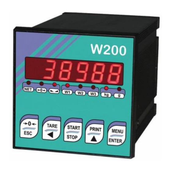
Page 14: Led And Key Function
LED AND KEY FUNCTION Function net weight (semi-automatic tare or preset tare) zero (deviation from zero not more than ±0.25 divisions) stability unit of measure: kg unit of measure: g Long press Short press Into menus (3 s) Cancel or return to previous Semi-automatic zero Tare resetting menu... -
Page 15: Menu Map
MENU MAP Into menus changes are applied right after pressing the ENTER key ( no further confirmation is required). SYSTEM PARAMETERS ... -
Page 16: Batching Constants
BATCHING CONSTANTS … … ... -
Page 17: Instrument Commissioning
INSTRUMENT COMMISSIONING Upon switch-on, the display shows in sequence: - → (ONLY in case of approved program); - instrument model (e.g.: ); - followed by the software code (e.g.: ); - program type: (base); ; ; ; ; ; (no active program);... -
Page 18: Programming Of System Parameters
PROGRAMMING OF SYSTEM PARAMETERS From the weight display, press simultaneously keys MENU and ESC to access the parameter setting. MENU/ENTER: to enter a menu/confirm the data entry. ▲: to modify the displayed figure or menu item. ◄: to select a new figure or modify the displayed menu item. ESC: to cancel and return to the previous menu. -
Page 19: Tare Weight Zero Setting
TARE WEIGHT ZERO SETTING This menu may also be accessed directly from the weight display, holding down the key for 3 seconds. Perform this procedure after having set the THEORETICAL CALIBRATION data. Use this function to set to zero the weight of the empty system after commissioning and then later on to compensate zero variations due to the presence of product residues. -
Page 20: Real Calibration (With Sample Weights)
REAL CALIBRATION (WITH SAMPLE WEIGHTS) After having performed the THEORETICAL CALIBRATION and TARE WEIGHT ZERO SETTING, this function allows correct calibration to be done using sample weights of known value and, if necessary, any deviations of the indicated value from the correct value to be corrected. -
Page 21: Filter On The Weight
FILTER ON THE WEIGHT Setting this parameter allows a stable weight display to be obtained. To increase the effect (weight more stable) increase the value (from 0 to 9, default 4). As seen in the diagram: - By confirming the message, the currently programmed filter value is displayed. - By changing and confirming the value, the weight is displayed and it will be possible to experimentally verify its stability. -
Page 22: Zero Parameters
ZERO PARAMETERS RESETTABLE WEIGHT SETTING FOR SMALL WEIGHT CHANGES (from 0 to max full scale; default: 300; considered decimals: 300 – 30.0 – 3.00 – 0.300): this parameter indicates the maximum weight value resettable by external contact, keypad or serial protocol. -
Page 23: Setting Units Of Measure
SETTING UNITS OF MEASURE These are the available units of measure: : kilograms grams : : tons pounds : : newtons : litres bars : : atmospheres pieces : newton metres : : kilogram metres other generic units of measure not included in the list : If the print function is enabled, the symbol corresponding to the selected unit of measure will be printed after the measured value. -
Page 24: Semi-Automatic Tare (Net/Gross)
SEMI-AUTOMATIC TARE (NET/GROSS) THE SEMI-AUTOMATIC TARE OPERATION IS LOST UPON INSTRUMENT POWER- OFF. To perform a net operation (SEMI-AUTOMATIC TARE), close the NET/GROSS input or press the TARE key for less than 3 seconds. The instrument displays the net weight (just set to zero) and the NET LED lights up. -
Page 25: Semi-Automatic Zero (Weight Zero-Setting For Small Variations)
While the net weight is displayed, keep ▲ pressed to display the gross weight. When the key is released the net weight will be displayed again. - IF A SEMI-AUTOMATIC TARE (NET) IS ENTERED, IT IS NOT POSSIBLE TO ACCESS THE ENTER PRESET TARE FUNCTION. - IF A PRESET TARE IS ENTERED, IT’S STILL POSSIBLE TO ACCESS THE SEMI- AUTOMATIC TARE (NET) FUNCTION. -
Page 26: Analog Output(Only For Instruments Where This Option Is Available)
ANALOG OUTPUT(ONLY FOR INSTRUMENTS WHERE THIS OPTION IS AVAILABLE) - : it selects the analog output type (4÷20 mA, 0÷20 mA, 0÷10 V, 0÷5 V, ±10 V, ±5 V; default: 4÷20 mA). For the output ±10 V and ±5 V the soldered jumper SW1 must be closed: ▫... -
Page 27: Serial Communication Setting
Minimum and maximum values which can be set for zero and full scale corrections: ANALOG OUTPUT TYPE Minimum Maximum 0÷10 V -0.150 10.200 0÷5 V -0.150 5.500 ±10 V -10.300 10.200 ±5 V -5.500 5.500 0÷20 mA -0.200 22.000 4÷20 mA -0.200 22.000 NOTE: the analog output may also be used in the opposite manner, i.e. - Page 28 - : continuous weight transmission protocol to RIP675, RIP6125C series remote displays; the remote display shows the net weight or gross weight according to its settings (set: = , = , = ). - : continuous weight transmission protocol to RIP675, RIP6125C series remote displays (set: ...
-
Page 29: Rs232 Serial Communication
RS232 SERIAL COMMUNICATION INSTRUMENT RS232 TXD RS232 RXD DB9-F RS485 SERIAL COMMUNICATION INSTRUMENT INSTRUMENT INSTRUMENT max 500 m 24 VDC RS485 + RS485 + RS485 - RS485 - CONVLAU If the RS485 network exceeds 100 metres in length or baud-rate over 9600 are used, two terminating resistors are needed at the ends of the network. -
Page 30: Weight Reading Via Serial Port
WEIGHT READING VIA SERIAL PORT Overview: By transmitting instrument, it means the one connected to the load cell. By receiving instrument, it means the one which receives the weight via serial port. This function allows the instrument to read the weight by another instrument (transmitting instrument) rather than by a load cell, via the RS485 or RS232 serial port. -
Page 31: Rs232 Connection
RS232 CONNECTION Transmitting instrument Receiving instrument TX RX INSTRUMENT Connector Signal RS232: TXD W200 TERMINAL RS232: RXD W200BOX RS232: SHIELD, GND COMMUNICATION SETTING Into the SERIAL COMMUNICATION SETTING section (see receiving instrument manual), select the desired serial port and operation mode: WEIRIP () or WEIMOD (). It’s not possible to enable this function on both serial ports;... -
Page 32: Weimod Mode
WEIMOD MODE Receiving instrument works as if the load cell is directly connected to the instrument. It’s therefore possible to perform calibrations and zero-settings on the receiving instrument. The used protocol is Modbus (the transmitting instrument works as "slave" and the receiving as "master"). Prior to set the ... -
Page 33: Alarm Relay Closure
ALARM RELAY CLOSURE The ALARM relay closing can be enabled or disabled for each of the following alarms: approval contact ();formula not programmed (); maximum weight exceeded (); minimum weight (); no increase in weight (); no decrease in weight (); fall ();... -
Page 34: Operation Settings
OPERATION SETTINGS : Select the switch conditions from the SET opening to the CYCLE END closing. - (default: ): time set in constants (). - (default: ): START input closure or ENTER key pressure. - ... -
Page 35: Programming Of Batching Constants
PROGRAMMING OF BATCHING CONSTANTS From weight display press MENU, then press ▲ several times until is displayed and confirm. MENU/ENTER: to enter a menu/confirm the data entry. ▲: to modify the displayed figure or menu item. ◄: to select a new figure or modify the displayed menu item. ESC: to cancel and return to the previous menu. -
Page 36: No Comparison Time
NO COMPARISON TIME (from 0.0 to max 999.9 seconds; default: 0.0): this is the instrument waiting time during batching, after the opening of PRESET, before comparing the weight with the programmed SET value. NO PRODUCT LOAD TIME (from 0.0 to max 999.9 seconds; default: 0.0): this parameter allows the product control during batching. -
Page 37: Tolerance
( only if is different from 0) (from 0 to max full scale; default: 0): this parameter indicates the limit within which the automatic fall is updated according to the parameter .By setting a low value is obtained more accurately but the length of the batchings could increase, because, if necessary, the AUTOMATIC fall is updated every cycle regardless of . -
Page 38: Autotare
SLOW ON (from 0 to max 9.9; default: 0): time in which the SET relay remains closed during the SLOW phase. By setting 0, the function is disabled. SLOW OFF (from 0 to max 9.9; default: 0): time in which the SET relay remains open during the SLOW phase. -
Page 39: Print At Cycle End
PRINT AT CYCLE END (default ): function enabling to print batching data at cycle end. - : print enabled - : print disabled NUMBER OF BATCHING PRINTOUTS (from 1 to 9; default: 1): number of copies of the batching printout. CHECKING PC PRESENCE ... -
Page 40: Formulas Programming
FORMULAS PROGRAMMING Select the formula that you wish to program and set and . It is possible to set max 99 formulas. … is NOT displayed if a SLOW value has been set in the constants (). In case of attempt in ... -
Page 41: Batching
BATCHING Note: In case of alarm, the batching may be canceled by pressing the ESC button or by closing the STOP input. After having selected the formula and set the desired number of batching cycles, the first batching cycle starts as follows: 1. -
Page 42: Batching Start From External Contact
- The CYCLE END contact is closed; - The display shows the weight preceded by the letter ; - Only if = : batching data (with date and time) are printed. - Only if = : consumption is stored. 11. -
Page 43: Resume Batching After A Power Cut
- To pause the batching at any time, press STOP, the prompt is displayed. Press ENTER to resume the batching or press again STOP to cancel it definitely. RESUME BATCHING AFTER A POWER CUT If a blackout occurs during the batching (unloading phase included), when power comes back ... -
Page 44: Alarms
ALARMS : it is displayed if, at batching start, the weight on the scale is higher than the minimum set in constants (). Press ESC to return to the weight displaying, press ENTER to cancel the alarm and continue with the batching. If the weight comes back below to the minimum set, the batching starts. - Page 45 maximum displayable value exceeded (value higher than 999999 or lower than -999999). : maximum displayable value exceeded on transmitting instrument (value higher than : 999999 or lower than -999999). : weight too high: zero setting not possible. : this message appears in the sample weight setting, in real calibration, after the fifth sample weight value has been entered.
-
Page 46: Printing Examples
PRINTING EXAMPLES If the printer has been set (see section SERIAL COMMUNICATION SETTING), from the weight display press the PRINT key for less than 3 seconds: - : prints the displayed weight; - : prints the constants (minimum weight, maximum weight, etc.); - : prints one or all of the formulas;... - Page 47 CONSTANTS PRINTOUT ----------------------- W200 LOAD Addr:01 DATE: 01/10/11 08:30:01 CONSTANTS MASS TIME SIC TIME WAIT TIME NCOMP TIME NLOAD TIME NUNLOAD FALL MANUAL SLOW TIME SLOWON TIME SLOWOF AUTOTARE UNLOAD GROSS TOTAL PRINT SLAVE BLACKOUT MANUAL RELAY ALARM RELAY TOL. FOR.
- Page 48 CONSUMPTION PRINTOUT ----------------------- W200 LOAD Addr:01 DATE: 01/10/11 08:30:38 CONSUMPTION 1148 kg 1456 kg TOTAL 2604 kg FROM: 01/09/11 09:11:13 If consumption is set to zero, it will also be printed: CONSUMPTION ERASED WEIGHT PRINTOUT ----------------------- W200 LOAD Addr:01 DATE: 12/09/11 14:48:12 GROSS 1204 kg 831 kg...
-
Page 49: Reserved For The Installer
RESERVED FOR THE INSTALLER MENU LOCKING Through this procedure, it’s possible to block the access to any menu on the instrument. Select the menu that you wish to lock: press ESC and ◄ simultaneously for 3 seconds, the display shows ... - Page 50 PROGRAM SELECTION: confirm and use the arrow keys to select the desired program: : basic program, setpoint management only. : to be used when the loaded weighing system correspond to not loaded cells and vice versa (product increases while weight on load cells actually decreases). : weight remote display program with setpoint.
-
Page 51: Keypad Or Display Locking
KEYPAD OR DISPLAY LOCKING Press ESC immediately followed by ▲ hold them down for about 5 seconds (this operation is also possible via the MODBUS and ASCII protocols): - : no lock. - : keypad lock: if active, when a key is pressed the message is displayed for 3 seconds. -
Page 52: Declaration Of Conformity - Eu
CERTIFICAZIONE DEL SISTEMA DI GARANZIA DELLA QUALITÀ DELLA PRODUZIONE email: laumas@laumas.it web: http://www.laumas.com LAUMAS Elettronica S.r.l. Tel. (+39) 0521 683124 - Fax (+39) 0521 681091 Fabbricante metrico Prot. N. 7340 Parma - R.E.A. PR N. 169833 - Reg. Imprese Via 1° Maggio 6 – 43022 Montechiarugolo (PR) Italy PR N.19393 - Registro Nazionale Pile N°...
Need help?
Do you have a question about the W200-C and is the answer not in the manual?
Questions and answers