Table of Contents
Advertisement
Quick Links
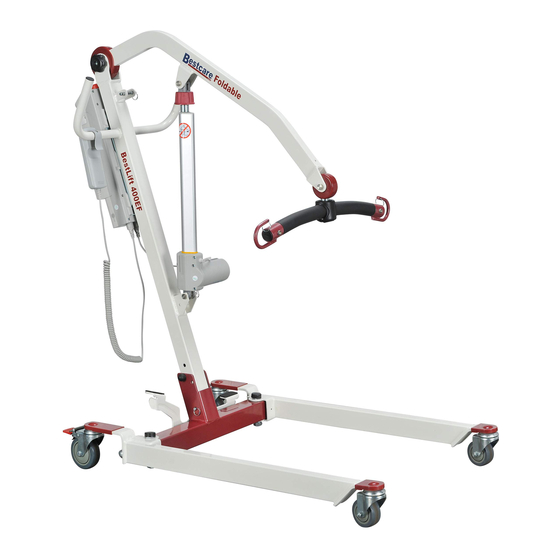
BESTLIFT®
F U L L B O D Y P A T I E N T L I F T
M o d e l : P L 4 0 0 E F
F o l d a b l e / P o r t a b l e
Folding Position #1 - Flat
Folding Position #2 - Standing
Ensure the product has been assembled according to the instructions in this
manual. All operators should read and understood the instructions for safe and
proper operation of the patient lift.
Advertisement
Table of Contents

Related Manuals for Bestcare BESTLIFT PL400EF


Summary of Contents for Bestcare BESTLIFT PL400EF
- Page 1 BESTLIFT® F U L L B O D Y P A T I E N T L I F T M o d e l : P L 4 0 0 E F F o l d a b l e / P o r t a b l e Folding Position #1 - Flat Folding Position #2 - Standing Ensure the product has been assembled according to the instructions in this...
-
Page 2: Date Of Manufacture
Thank you for choosing Bestcare! To better serve you, please record the following information for future use: Supplier Name: ___________________________________________ Supplier Telephone: ________________________________________ Product Serial Number: _____________________________________ Date of Purchase: _________________________________________ Date of Manufacture ® BestLift PL400EF MAX LOAD: 400LB... -
Page 3: Product Description
Product Description The Bestlift PL400EF allows the patient to be lifted and transferred safely with minimal physical effort provided by the operator. This is due to it being a full electric lift . With the PL400EF, patients can be lifted from floor to bed with ease. -
Page 4: Definitions & Symbols
DEFINITIONS & SYMBOLS n this manual the user refers to the patient or resident and may be used interchangeably at different times. Caregiver refers to the operator or person who is assisting with the transfer. Symbols used in this manual and on the product and their meanings: Warning! Failure to heed this warning may Do Not Bleach. -
Page 5: Safety Instructions
• While being lifted in a sling, always keep the user/patient centered over the base and facing the caregiver operating the lifter. • Never leave the user/patient unattended during lifting. Service personnel may contact Bestcare for any information, instructions, or certain parts for servicing purpose. - Page 6 • DO NOT replace any components of the lift without consulting with Bestcare, and must follow proper instruction from Bestcare when replacing any components. • DO NOT service any parts of the lift while in use with a patient.
-
Page 7: Features And Overview
PROPRIETARY AND CONFIDENTIAL 120-400 THE INFORMATION CONTAINED IN THIS MATERIAL: DESCRIPTION: DRAWING IS THE SOLE PROPERTY OF BESTCARE LLC. ANY REPRODUCTION IN PART FINISH: SCALE: SHEET: 1 of 1 OR AS A WHOLE WITHOUT THE WRITTEN PERMISSION OF BESTCARE LLC IS PROHIBITED. - Page 8 mm (in) 1841.2 (72.5) 1237.5 (48.7) 603.7 (23.8) 526.7 (20.7) 812.8 (32.0) 771.4 (30.4) 576.6 (22.7) 336.4 (13.2) 544.1 (21.4) 258.4 (10.2) 491.0 (19.3) 121.0 (4.8) 20.3 (0.8) 1198.8 (47.2) 657.5 (25.9) 377.1 (14.8)...
-
Page 9: Specifications And Options
H Base Closed Turning Diameter 1306.5mm 89.7 lb Unloaded Lift Weight 40.8 kg * Bestcare is committed to continuous improvements of our products therefore the specification, dimensions, and features listed above are for guidance only and are subject to change without prior notice. - Page 10 Step 1: Remove folded lift from box Step 2: Secure the stand to the mast. Make sure the tab on the standing bracket sit in the top hole on the mast, and insert the screw to the lower hole as follows. Step 3: Remove the quick release pin that is securing the mast Step 4: Lift the mast upright.
- Page 11 Step 5: Insert the pin to the bottom hole to secure the mast in upright position Step 6: Remove the pin that is securing the boom Step 7: Remove lower actuator pin...
- Page 12 Step 8: Move the boom out of the way, and install the lower end of the actuator as follows. It is critical to have the motor part of the actuator to face the same direction as the big arrow as follows. Step 9: Install the upper end of actuator and reinsert the quick release pin to secure it.
- Page 13 Step 10: Installing the Control box on the Lift P E R M I S S I O N O F B E S T C A R E L L C I S P R O H I B I T E D . 1 o f 1 O R A S A W H O L E W I T H O U T T H E W R I T T E N F I N I S H :...
- Page 14 Folding the PL400EF for Storage or Transport Step 1: Spreader bar at lowest position Step 2: Folding the boom Step 3: Folding the mast Step 4: Standing position Warning - The lift may fall and cause bodily injury if it is not secured against the wall.
- Page 15 Operating Instructions Double check all assemblies for tightness and read operating instructions carefully prior to use. For optimum performance the lift should be transported and stored in following condition range: • -25°C to +5°C (-13°F to 41°F), and • +5°C to +35°C (41°F to 95°F) at a non-condensing relative humidity 0% to 90% •...
- Page 16 Power Control Unit Overview Emergency Stop Button Up / Down Button Battery Pack Release Handle LCD Display Panel Battery Pack Clear Contact Plastic Cover Charger DC In Not Used Additional Battery Pack (Optional) Actuator Hand Control Charging Cradle (Optional) 1. Connect Actuator as shown above. 2.
- Page 17 Pressed In Release LCD Display Panel Signs When the emergency stop button is released, the LCD Display Panel will show one of the four signs below. • The sign will display for 5 seconds. • Then the lift will go into standby mode and the sign disappears. •...
- Page 18 Operating Lift: Using Hand Control LED Indicator Lifting * Green = In Use * Blank = Standby Lowering Operating Lift: Using LCD Display Panel...
- Page 19 Warning! - Battery Low and Charging is Needed If the battery needs to be charged, the LCD Display Panel will show a blinking low battery sign shown on the left either when the emergency stop button is released or when a button on the LCD Display Panel is pressed.
- Page 20 Available slings compatible with Patient Lift Sling Type Material Sizes Mesh M, L Universal Polyester M, L, XXL Mesh S, M, L Universal with Head Support Polyester S, M, L, XXL Universal Disposable Nonwoven, Disposable M, L Universal Disposable with Head Support Nonwoven, Disposable S, M, L, XXL Sani...
- Page 21 Sling Hook-Up Guide 2 Point S-Bar 6 Point S-Bar Hook up A Point 1 Hook up A Point 1 Hook up B Point 2 Hook up B Point 2 Insert D through C Insert D through C Hook up D Point 1 Hook up D Point 5...
- Page 22 Transfer From Bed to Wheelchair 1. User/patient should be in the center of the bed. 2. Position user onto his/her side by rolling user towards you. 3. Roll the sling in half. The handle on the back section should face outward when the sling is fitted.
-
Page 23: Maintenance And Inspection
• With proper use and care, the expected lifetime of the lift is 10 years or 20,000 cycles. • The expected lifetime of the electrical components are 3 years. • Contact Bestcare for any recycling information First Received Monthly Every 3 Months Boom &... -
Page 24: Cleaning And Disinfecting
REPLACE a sling when it shows signs of deterioration. Deterioration of sling • Contact Bestcare for “Guideline for Identifying Deteriorated Slings” if needed. Disinfecting of the lift and sling • Inspect slings prior to each use for contamination from previous use. -
Page 25: Troubleshooting Guide
Troubleshooting Guide The following list of encountered problems and solutions will assist you in determining what may be causing your patient lift not to function as designed. If you have a problem occurring which is not listed below please contact your dealer or technical support for help. Do not attempt to repair or replace components or parts on your lift as this may void your warranty or cause further problems that may result in patient injury. -
Page 26: Emergency Lowering Mechanism
Emergency Lowering Mechanism Contact your dealer immediately if standard troubleshooting techniques do not correct the failure. Do not attempt to lift until all failure and safety issues have been resolved. In case of lift failure, please follow the procedures below to safely lower the user. The Emergency Lowering Device is located at the top of the actuator shaft. - Page 27 RETURN GOODS POLICY Patient lifts may not be returned unless the wrong lift is shipped in error by Bestcare or the lift is heavily damaged or defective out of the box. For all other items, purchaser may request a RA for purchased goods within thirty (30) days of purchase invoice date. All returns must be received by Bestcare no later than thirty (30) days after authorization or the RA will be voided.
- Page 28 Bestcare LLC 2920 Pacific Drive www.bestcarellc.com | © 2021 Bestcare LLC Norcross, GA 30071 Ver 2021.09...
Need help?
Do you have a question about the BESTLIFT PL400EF and is the answer not in the manual?
Questions and answers