Table of Contents
Advertisement
Quick Links
Using the TPS53310EVM-755, A 3-A Eco-mode™
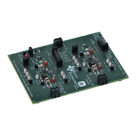
The TPS53310EVM-755 evaluation module (EVM) is a high-efficiency evaluation platform with two
TPS53310 3-A, integrated FET, step-down converters working in a Master-Slave synchronization scheme.
The two outputs are 1.5 V/3 A (master) and 1.2 V/3 A (slave) from a 3.3-V or 5-V input bus. The EVM
uses the TPS53310 synchronous buck controller with integrated switcher.
...................................................................................................................
1
1.1
1.2
2
....................................................................................................................
3
...................................................................................................................
4
4.1
4.2
5
5.1
5.2
5.3
5.4
5.5
5.6
6
6.1
6.2
6.3
6.4
7
7.1
7.2
7.3
7.4
7.5
7.6
7.7
7.8
7.9
7.10
7.11
7.12
7.13
7.14
8
9
Eco-mode is a trademark of Texas Instruments.
SLUU826 - January 2012
Submit Documentation Feedback
Integrated Switcher With Master-Slave
................................................................................................
.............................................................................................................
....................................................................................
.....................................................................................................
.......................................................................................
................................................................................................................
....................................................................................
.................................................................................
.................................................................................
......................................................................................
....................................................................................
......................................................................................
..............................................................................................................
.................................................................................
................................................................................................
............................................................................................
..........................................................................................................
..................................................................................................
...................................................................................................
..............................................................................................
..............................................................................
...........................................................................................
.........................................................................................
.........................................................................................
...................................................................................
...................................................................................................
................................................................................
.............................................................................................................
Using the TPS53310EVM-755, A 3-A Eco-mode™ Integrated Switcher With
Copyright © 2012, Texas Instruments Incorporated
Contents
..............................................
................................................................
.............................................................................
............................................................................
................................................
............................................................................
User's Guide
SLUU826 - January 2012
3
3
3
3
5
6
6
7
8
8
8
8
8
9
9
9
9
9
10
10
10
11
11
12
12
13
13
14
14
15
15
16
16
17
17
18
22
1
Master-Slave
Advertisement
Table of Contents

Related Manuals for Texas Instruments TPS53310EVM-755


Summary of Contents for Texas Instruments TPS53310EVM-755
-
Page 1: Table Of Contents
Using the TPS53310EVM-755, A 3-A Eco-mode™ Integrated Switcher With Master-Slave The TPS53310EVM-755 evaluation module (EVM) is a high-efficiency evaluation platform with two TPS53310 3-A, integrated FET, step-down converters working in a Master-Slave synchronization scheme. The two outputs are 1.5 V/3 A (master) and 1.2 V/3 A (slave) from a 3.3-V or 5-V input bus. The EVM uses the TPS53310 synchronous buck controller with integrated switcher. - Page 2 TPS53310EVM-755 Switching Node at No Load (5 Vin, 1.5 V/0 A DE Mode) ....TPS53310EVM-755 Synchronization (3.3 Vin, 1.5 V/3 A, 1.2 V/3 A 180° Synchronization) TPS53310EVM-755 Synchronization (3.3 Vin, 1.5 V/3 A, 1.2 V/3 A 180° Synchronization, Then Turn Off ........................Master) ..........
-
Page 3: Description
Description The TPS53310EVM-755 uses a regulated 3.3-V or 5-V bus to produce outputs at up to 3 A of load current. The output is 1.5-V master and 1.2-V slave. The TPS53310EVM-755 is designed to demonstrate the TPS53310 in a typical low-voltage application while providing test points to evaluate the performance of the TPS53310. - Page 4 87.32 Operating temperature ºC Note: Jumpers set to default locations; see Section 5 of this user’s guide. SLUU826 – January 2012 Using the TPS53310EVM-755, A 3-A Eco-mode™ Integrated Switcher With Master-Slave Submit Documentation Feedback Copyright © 2012, Texas Instruments Incorporated...
-
Page 5: Schematic
Schematic www.ti.com Schematic Figure 1. TPS53310EVM-755 Schematic SLUU826 – January 2012 Using the TPS53310EVM-755, A 3-A Eco-mode™ Integrated Switcher With Master-Slave Submit Documentation Feedback Copyright © 2012, Texas Instruments Incorporated... -
Page 6: Test Setup
3. J8 to LOAD2 the minimum recommended wire size is AWG16, with the total length of wire less than 4 feet (2-foot input, 2-foot return) SLUU826 – January 2012 Using the TPS53310EVM-755, A 3-A Eco-mode™ Integrated Switcher With Master-Slave Submit Documentation Feedback... -
Page 7: Recommended Test Setup
Figure 3. TPS53310EVM-755 Recommended Test Setup Figure 3 is the recommended test setup to evaluate the TPS53310EVM-755. When working at an ESD workstation, make sure that any wrist straps, bootstraps, or mats are connected referencing the user to earth ground before handling the EVM. -
Page 8: Configuration
Table 5. Synchronization Selection Jumper set to Master and Slave Synchronization Jumper shorts on J5 No Jumper on J5 Using the TPS53310EVM-755, A 3-A Eco-mode™ Integrated Switcher With SLUU826 – January 2012 Master-Slave Submit Documentation Feedback Copyright © 2012, Texas Instruments Incorporated... -
Page 9: Master Enable (J4: En_Mst)
7. Disconnect isolate transformer from the bode plot setup before making other measurements. (Signal injection into feedback may interfere with accuracy of other measurement.) SLUU826 – January 2012 Using the TPS53310EVM-755, A 3-A Eco-mode™ Integrated Switcher With Master-Slave Submit Documentation Feedback... -
Page 10: List Of Test Points
3. Shut down oscilloscope. Performance Data and Typical Characteristic Curves Figure 4 through Figure 17 present typical performance curves for TPS53310EVM-755. Jumpers set to default locations; see Section SLUU826 – January 2012 Using the TPS53310EVM-755, A 3-A Eco-mode™ Integrated Switcher With... -
Page 11: Efficiency
3.3Vin, 1.2Vout, HEF 5Vin, 1.2Vout, HEF I - Output Current - A Figure 5. TPS53310EVM-755 Load Regulation SLUU826 – January 2012 Using the TPS53310EVM-755, A 3-A Eco-mode™ Integrated Switcher With Master-Slave Submit Documentation Feedback Copyright © 2012, Texas Instruments Incorporated... -
Page 12: Line Regulation
1.5-V Output Ripple TPS53310EVM-755 Test condition: 3.3Vin, 1.5V/3A, FCCM Output Ripple CH1: 1.5V_MST Output Ripple Figure 7. TPS53310EVM-755 Output Ripple (3.3 Vin, 1.5 V/3 A) SLUU826 – January 2012 Using the TPS53310EVM-755, A 3-A Eco-mode™ Integrated Switcher With Master-Slave Submit Documentation Feedback... -
Page 13: V Switching Node At Full Load
TPS53310EVM-755 Test condition: 5Vin, 1.5V/0A, DE 1.5Vout Switching Node CH2: SW_MST Figure 9. TPS53310EVM-755 Switching Node at No Load (5 Vin, 1.5 V/0 A DE Mode) SLUU826 – January 2012 Using the TPS53310EVM-755, A 3-A Eco-mode™ Integrated Switcher With Master-Slave Submit Documentation Feedback Copyright ©... -
Page 14: Master-Slave 180° Synchronization
Figure 11. TPS53310EVM-755 Synchronization (3.3 Vin, 1.5 V/3 A, 1.2 V/3 A 180° Synchronization, Then Turn Off Master) SLUU826 – January 2012 Using the TPS53310EVM-755, A 3-A Eco-mode™ Integrated Switcher With Master-Slave Submit Documentation Feedback Copyright © 2012, Texas Instruments Incorporated... -
Page 15: V Output Transient
Test condition: 5Vin, 1.5V/0A-3A, FCCM Transient Response CH1: 1.5Voutput CH2: SW_MST CH3: 1.5Voutput current 0A-3A Figure 12. TPS53310EVM-755 1.5-V Output Transient (5 Vin, 1.5 V/0 A-3 A ) 7.10 1.5-V Turnon Waveform TPS53310EVM-755 Test condition: 3.3Vin, 1.5V/3A, FCCM 1.5V Enable Start up CH1: EN_MST CH2: 1.5Voutput... -
Page 16: 7.11 1.5-V Turnoff Waveform
CH1: 1.5Vout CH2: SW_MST CH3: PG_MST Figure 15. TPS53310EVM-755 Hiccup OCP Waveform (5 Vin, 1.5 V/5.5 A OCP) SLUU826 – January 2012 Using the TPS53310EVM-755, A 3-A Eco-mode™ Integrated Switcher With Master-Slave Submit Documentation Feedback Copyright © 2012, Texas Instruments Incorporated... -
Page 17: 7.13 1.5-V Bode Plot
Performance Data and Typical Characteristic Curves www.ti.com 7.13 1.5-V Bode Plot Figure 16. TPS53310EVM-755 Bode Plot (3.3 Vin, 1.5 V/3 A) 7.14 EVM Top Board Thermal Image Figure 17. TPS53310EVM-755 Top-Side Thermal Image (3.3 Vin, 1.5 V/3 A, 1.2 V/3 A) SLUU826 –... -
Page 18: Evm Assembly Drawings And Pcb Layout
The EVM has been designed using a four-layer circuit board with 2 oz of copper on the outside layers. EXAS NSTRUMENT Figure 18. TPS53310EVM-755 Top Layer Assembly Drawing, Top View SLUU826 – January 2012 Using the TPS53310EVM-755, A 3-A Eco-mode™ Integrated Switcher With Master-Slave Submit Documentation Feedback Copyright ©... -
Page 19: Tps53310Evm-755 Bottom Assembly Drawing, Bottom View
EVM Assembly Drawings and PCB Layout www.ti.com Figure 19. TPS53310EVM-755 Bottom Assembly Drawing, Bottom View Figure 20. TPS53310EVM-755 Top Copper, Top View SLUU826 – January 2012 Using the TPS53310EVM-755, A 3-A Eco-mode™ Integrated Switcher With Master-Slave Submit Documentation Feedback Copyright © 2012, Texas Instruments Incorporated... -
Page 20: Tps53310Evm-755 Internal Layer 2, Top View
Figure 21. TPS53310EVM-755 Internal Layer 2, Top View Figure 22. TPS53310EVM-755 Internal Layer 3, Top View SLUU826 – January 2012 Using the TPS53310EVM-755, A 3-A Eco-mode™ Integrated Switcher With Master-Slave Submit Documentation Feedback Copyright © 2012, Texas Instruments Incorporated... -
Page 21: Tps53310Evm-755 Bottom Copper, Top View
EVM Assembly Drawings and PCB Layout www.ti.com Figure 23. TPS53310EVM-755 Bottom Copper, Top View SLUU826 – January 2012 Using the TPS53310EVM-755, A 3-A Eco-mode™ Integrated Switcher With Master-Slave Submit Documentation Feedback Copyright © 2012, Texas Instruments Incorporated... -
Page 22: Bill Of Materials
IC, 150mA, Low Iq, Wide bandwidth, LDO Linear regulator, SC70 TPS71733DCKR U2, U3 IC, 3A Step-down regulator with integrated switcher, QFN-16 TPS53310RGT SLUU826 – January 2012 Using the TPS53310EVM-755, A 3-A Eco-mode™ Integrated Switcher With Master-Slave Submit Documentation Feedback Copyright © 2012, Texas Instruments Incorporated... - Page 23 Evaluation Board/Kit Important Notice Texas Instruments (TI) provides the enclosed product(s) under the following conditions: This evaluation board/kit is intended for use for ENGINEERING DEVELOPMENT, DEMONSTRATION, OR EVALUATION PURPOSES ONLY and is not considered by TI to be a finished end-product fit for general consumer use. Persons handling the product(s) must have electronics training and observe good engineering practice standards.
- Page 24 Any exceptions to this are strictly prohibited and unauthorized by Texas Instruments unless user has obtained appropriate experimental/development licenses from local regulatory authorities, which is responsibility of user including its acceptable authorization.
- Page 25 FCC Interference Statement for Class B EVM devices This equipment has been tested and found to comply with the limits for a Class B digital device, pursuant to part 15 of the FCC Rules. These limits are designed to provide reasonable protection against harmful interference in a residential installation. This equipment generates, uses and can radiate radio frequency energy and, if not installed and used in accordance with the instructions, may cause harmful interference to radio communications.
- Page 26 Also, please do not transfer this product, unless you give the same notice above to the transferee. Please note that if you could not follow the instructions above, you will be subject to penalties of Radio Law of Japan. Texas Instruments Japan Limited (address) 24-1, Nishi-Shinjuku 6 chome, Shinjuku-ku, Tokyo, Japan http://www.tij.co.jp...
- Page 27 FDA Class III or similar classification, then you must specifically notify TI of such intent and enter into a separate Assurance and Indemnity Agreement. Mailing Address: Texas Instruments, Post Office Box 655303, Dallas, Texas 75265 Copyright © 2012, Texas Instruments Incorporated...
- Page 28 IMPORTANT NOTICE Texas Instruments Incorporated and its subsidiaries (TI) reserve the right to make corrections, enhancements, improvements and other changes to its semiconductor products and services per JESD46, latest issue, and to discontinue any product or service per JESD48, latest issue.
- Page 29 Mouser Electronics Authorized Distributor Click to View Pricing, Inventory, Delivery & Lifecycle Information: Texas Instruments TPS53310EVM-755...
Need help?
Do you have a question about the TPS53310EVM-755 and is the answer not in the manual?
Questions and answers