Advertisement
Table of Contents
- 1 Precautions and Safety Information
- 2 Environmental Conditions
- 3 VIGIL Eclipse5 Overview
- 4 General Safety Precautions
- 5 General Safety Precautions (Cont.)
- 6 BVECASE5 & BVECASE5BATT Mounting Guidelines
- 7 BVECASE5 Mounting Holes and Knockout Positions
- 8 BVECASE5BATT Mounting Holes
- Download this manual
Advertisement
Table of Contents

Subscribe to Our Youtube Channel
Related Manuals for Baldwin Boxall BVECASE5BATT


Summary of Contents for Baldwin Boxall BVECASE5BATT
- Page 1 BVECASE5 20/12/2021 Issue 3 ECR 4453 VIGIL Eclipse5 (BVECASE5 & BVECASE5BATT Installation Details Baldwin Boxall Communications Ltd. Wealden Industrial Estate, Farningham Road Crowborough, East Sussex, TN6 2JR Telephone: 01892 664422 Website: www.baldwinboxall.co.uk Email: hello@baldwinboxall.co.uk...
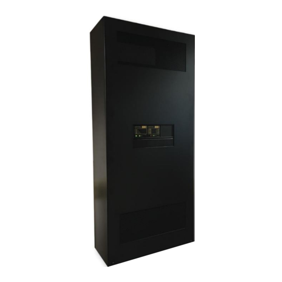
- Page 2 Network Interface modules (if required), suitable batteries and a choice of up to four amplifier mainframes. If more than two amplifier mainframes are installed then an external Battery Box (BVECASE5BATT) is supplied that is designed to be floor mounted, with the BVECASE5 installed directly above it.
- Page 3 General Safety Precautions A U T I O N These Safety Precautions apply to assembled systems, however they may not all be applicable to every item within that system. Failure to follow these instructions and guidelines may cause personal injury and/or damage to the equipment. A R N I N G This equipment is intended for continuous operation and as such should be permanently connected to the mains supply.
- Page 4 General Safety Precautions (cont.) A R N I N G Note that this equipment uses battery backup, and if the Mains Supply is disconnected Hazardous voltages will still be accessible on the terminals marked with the "High Voltage" symbol. A R N I N G The 24V DC batteries used within this system can deliver extremely high currents that can cause fire or burns.
- Page 5 The BVECASE5 and BVECASE5BATT are designed to be installed together, with the BVECASE5BATT floor mounted and the BVECASE5 installed directly above. Care should be taken when installing the BVECASE5 to allow 780mm for a BVECASE5BATT to be installed directly underneath to allow for future expansion.
- Page 6 BVECASE5 Mounting Holes and Knockout Positions Note: The BVECASE5 has been designed to allow cable entry from the top (via knockouts) or via the removable access plate in the rear panel. There is no requirement for ventilation or space either side of the installed position as all terminations can be accessed and maintenance operations can be performed from the front of the unit.
- Page 7 BVECASE5BATT Mounting Holes Note: Ensure the internal battery mounting plinth is fitted to the base of the battery box before installing the batteries. Note: The Adjustable feet should be set to raise the battery box to the level of the BVECASE5 installed directly above it.
Need help?
Do you have a question about the BVECASE5BATT and is the answer not in the manual?
Questions and answers