Advertisement
IBVE
Issue 6 14/07/2004
ECR 1597
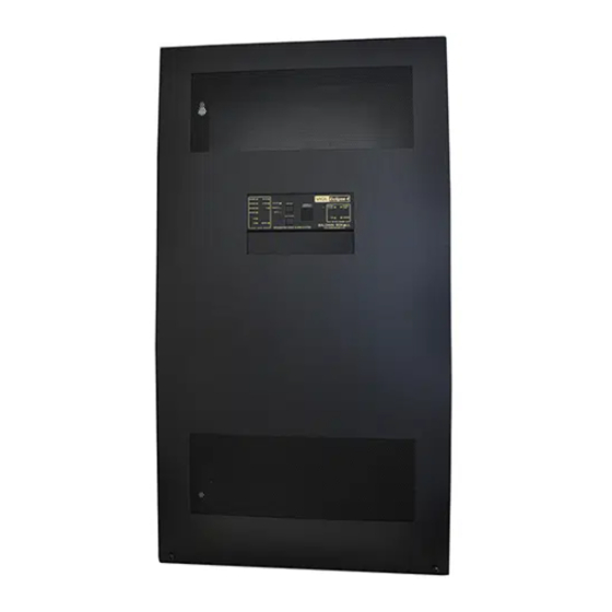
VIGIL ECLIPSE
(Compact Software Version COMP4)
Integrated Voice Alarm System
Installation and Operating
Instructions
Baldwin Boxall Communications Ltd.
Wealden Industrial Estate, Farningham Road
Crowborough, East Sussex, TN6 2JR
C O M M U N I C A T I O N S
Telephone: 01892 664422 Fax: 01892 663146
Website: www.baldwinboxall.co.uk
Email: mail@baldwinboxall.co.uk
Advertisement
Table of Contents

Related Manuals for Baldwin Boxall VIGIL ECLIPSE


Summary of Contents for Baldwin Boxall VIGIL ECLIPSE
- Page 1 (Compact Software Version COMP4) Integrated Voice Alarm System Installation and Operating Instructions Baldwin Boxall Communications Ltd. Wealden Industrial Estate, Farningham Road Crowborough, East Sussex, TN6 2JR C O M M U N I C A T I O N S Telephone: 01892 664422 Fax: 01892 663146 Website: www.baldwinboxall.co.uk...
- Page 2 INDEX ……… Index ……… General Description ……… Mounting Instructions 5 - 6 ……... Installation Instructions 7 - 9 ……… Terminations and Connections ……… Typical Connection Diagram Attachment 1 ……… BVCOM Instruction Manual Attachment 2 ……… BVSMP Instruction Manual Attachment 3 ……… BV440M Instruction Manual Attachment 4 ………...
-
Page 3: General Description
Bracket supplied. The system is powered by a 230V AC 50-60Hz power supply with internal battery backup. The VIGIL Eclipse is supplied with the necessary number of BEL1 end of line monitoring devices to provide full monitoring. C O M... -
Page 4: Mounting Instructions
MOUNTING INSTRUCTIONS When delivered from the factory, the Eclipse will be supplied on a pallet with a Wall Mounting Bracket, and depending on the version with Amplifier frames, Microphones (if ordered), batteries, and BEL1 modules packed separately. The mounting bracket should be fixed to wall first using suitable bolts for the required loading. -
Page 5: Installation Instructions
INSTALLATION INSTRUCTIONS Mainframe Assembly Fit mainframe(s) into Eclipse and connect up as indicated on all cable looms. Make sure flying lead from mainframe power loom is connected to BVSMP chassis earth point. Microphone(s) Installation Connect suitable (i.e. fire resistant) cable from the microphone(s) to the connections on the Termination Board inside the Eclipse. - Page 6 INSTALLATION INSTRUCTIONS Continued Switch Any Unused Fire Mic Select Lines To ‘ON’. FIG 3 Switch To ‘ON’ For Continuous Surveillance. Switch Any Unused Line Fault Inputs To ‘ON’. FIG 4 Fig 5 - 6 - Issue 6...
-
Page 7: Terminations And Connections
TERMINATIONS AND CONNECTIONS Termination Function Description Compact Board Terminal FM 1 +24V +24V @ 0.5A max via resettable fuse F1 P1 pin10 FM 1 Busy Closes to 0V if any zone is in use P1 pin 9 FM 1 Access All Close to 0V via 1k2 to call all zones P1 pin 8 FM 1... - Page 8 TERMINATIONS AND CONNECTIONS Continued Termination Function Description Compact Board Terminal Zone 4 select ( Close to 0V to access or P5 pin 7 Zone 3 select via 4k7 potentiometer P5 pin 6 Zone 2 select if remote volume control P5 pin 5 Zone 1 select Is required ) P5 pin 4...
- Page 9 TERMINATIONS AND CONNECTIONS Continued Termination Function Description Board AMP1 100V line loudspeaker output 1 AMP1 Earth for BEL1 AMP1 100V line loudspeaker output 1 AMP2 100V line loudspeaker output 2 AMP2 Earth for BEL1 AMP2 100V line loudspeaker output 2 AMP3 100V line loudspeaker output 3 AMP3...
- Page 10 Typical Connection Diagram For A Four Zone VA System - 10 - Issue 6...
Need help?
Do you have a question about the VIGIL ECLIPSE and is the answer not in the manual?
Questions and answers
What would cause these issues
The available context does not provide specific details about issues that can occur with the Baldwin Boxall VIGIL ECLIPSE. However, potential issues with voice alarm or public address systems like this may include faulty connections, power supply failures, incorrect terminations, or end-of-line resistor mismatches. If more details are needed, referring to the troubleshooting section of the manual may help.
This answer is automatically generated