Table of Contents
Advertisement
Quick Links
IBVR20
08/08/2003
ECR 1500
VIGIL BVR20 - Microdrive
(For use with software issue BVR8.43)
SETUP
INSTRUCTIONS
Baldwin Boxall Communications Ltd.
Wealden Industrial Estate, Farningham Road
Crowborough, East Sussex, TN6 2JR
C O M M U N I C A T I O N S
Telephone: 01892 664422
Fax: 01892 663146
Website: www.baldwinboxall.co.uk
Email: mail@baldwinboxall.co.uk
Advertisement
Table of Contents

Subscribe to Our Youtube Channel
Related Manuals for Baldwin Boxall VIGIL BVR20


Summary of Contents for Baldwin Boxall VIGIL BVR20
- Page 1 IBVR20 08/08/2003 ECR 1500 VIGIL BVR20 - Microdrive (For use with software issue BVR8.43) SETUP INSTRUCTIONS Baldwin Boxall Communications Ltd. Wealden Industrial Estate, Farningham Road Crowborough, East Sussex, TN6 2JR C O M M U N I C A T I O N S...
-
Page 2: Table Of Contents
CONTENTS VIGIL BVR20 MICRODRIVE ....................3 BVR802 – Quad EPROM based digital message module ............4 BVR20 FRONT PANEL CONTROLS AND INDICATORS............5 DESCRIPTION OF FRONT PANEL CONTROLS AND INDICATORS........6 MAINTENANCE OF THE BVR20 ....................7 FAULT REPORTING AND STATUS PAGES ................8 HOW TO MONITOR EITHER AN INPUT OR OUTPUT CHANNEL SIGNAL ......11 HOW TO VIEW OR CHANGE AN OUTPUT CHANNEL SETTING. -
Page 3: Vigil Bvr20 Microdrive
VIGIL BVR20 MICRODRIVE The BVR20 (Microdrive) is the heart of the Voice Alarm system that accepts all of the audio inputs and provides the outputs for the whole voice alarm system. Up to 20 audio inputs can be routed through to up to 20 outputs (zones) in any configuration. The inputs range from any microphone or line level source to the emergency messages and background music. -
Page 4: Bvr802 - Quad Eprom Based Digital Message Module
BVR802 – Quad EPROM based digital message module This card enables four OPT 402 message modules to be fitted allowing up to seven messages to be stored on one card. It has the following features:- Three dual messages plus one single message – 7 x 32 seconds in length or four at 64 seconds. Each message has output attenuation. -
Page 5: Bvr20 Front Panel Controls And Indicators
BVR20 FRONT PANEL CONTROLS AND INDICATORS Page 5 IBVR20 software 8.43.doc Issue 1... -
Page 6: Description Of Front Panel Controls And Indicators
DESCRIPTION OF FRONT PANEL CONTROLS AND INDICATORS ‘System Healthy’ Will illuminate when no faults are detected. If illuminated a critical CPU failure has occurred. ‘CPU Fault’ LED Only Fire Mic 1 ‘All Call’ function will operate as this input bypasses all CPU control as required by BS5839 pt 8. Will flash and a buzzer will sound when a Fault is detected ‘Common Fault’... -
Page 7: Maintenance Of The Bvr20
MAINTENANCE OF THE BVR20 If a fault is suspected on any of the BVR20 modules, simple substitution with a spare can be carried out as first-line maintenance. Before removing any module ensure that the two DC supplies are disconnected by removing the lower 8-way blue plug from the CPU module. The CPU module BVRCPU –... -
Page 8: Fault Reporting And Status Pages
FAULT REPORTING AND STATUS PAGES (Available in “normal” mode i.e. without turning the “system configuration” key.) In normal operation mode this unit indicates the condition of the system via the front panel display. Under normal - i.e. non-fault - conditions the green healthy indicator will illuminate, the fault relay will be energised and the sounder will be silent. - Page 9 Page 5 examples. ------------------------------------------ | RESERVE AMPLIFIERS|1 XX|2 OK|3 OK|4 OK | FAULTS In use|- --|- --|- --|- -- | ------------------------------------------ XX indicates that reserve amplifier 1 has a fault. ------------------------------------------ | RESERVE AMPLIFIERS|1 OK|2 OK|3 OK|4 OK | | NO FAULTS In use|A 01|- --|- --|- -- | ------------------------------------------ Reserve amplifier 1 in use on loudspeaker circuit 1A.
- Page 10 Page11. Page microphones 1 to 4 if monitored. ------------------------------------------ | PAGE MICS | AUDIO 1=OK| ACCESS 1=OK | | NO FAULTS |2=OK 3=OK 4=OK|2=OK 3=OK 4=OK | ------------------------------------------ Page microphones 1 to 4 ------------------------------------------ | PAGE MICS | AUDIO 1=OK| ACCESS 1=OK | FAULTS |2=XX 3=OK 4=OK|2=OK 3=OK 4=OK |...
-
Page 11: How To Monitor Either An Input Or Output Channel Signal
HOW TO MONITOR EITHER AN INPUT OR OUTPUT CHANNEL SIGNAL VIA THE INTERNAL LOUDSPEAKER Use the “Page Up” or “Page Down” keys to select the page shown below. ------------------------------------------ |OUTPUT ZONE|INPUT SOURCE|VOLUME | | MONITOR |00 ------------------------------------------ Press the “→” or “←” cursor keys and move along to the INPUT SOURCE or OUTPUT ZONE window. -
Page 12: How To View Or Change An Output Channel Setting
The display will show the software version, in this example 08.41. ------------------------------------------ | BVR 20 VOICE ALARM Version 08.41 06.19 | BALDWIN BOXALL COMMUNICATIONS ------------------------------------------ 2. Press the Page down key. The display invites you to enter your 4 digit access code to enable adjustments. There are 4 access levels. - Page 13 Note: Surveillance for inputs 1-9 is sampled from output 1 and therefore associated inputs on output 1 must be set to a value greater than 05 to prevent input audio faults. Surveillance for inputs 10-16 is sampled from outputs 2-8 respectfully, i.e. input 10 from output 2, input 16 from output 8 and therefore the associated inputs on the relevant outputs must be set to a value greater than 05 to prevent input audio faults.
- Page 14 ------------------------------------------ | OUT 01|CHIME|SURV (A=00 B=00)|ANS (-00 | 00|Out 00|Off |Sens 00 | ------------------------------------------ ↑ To select surveillance, move the cursor along until it flashes beneath the surveillance out window shown above. If surveillance is not required press 0 and the display will show 00. If surveillance is required press 9 and the display will show 09.
- Page 15 Ambient noise sensor, only available outputs 1-16. Volume reduction factor ( –12 minimum output), (--00 maximum output). ↓ ------------------------------------------ | OUT 01|CHIME|SURV (A=00 B=00)|ANS (-00 | 00|Out 09|20K A+B+Res|Sens 00 | ------------------------------------------ ↑ Move the cursor along until it flashes beneath the sensor window, shown above. If ambient noise sensing is not required or the maximum output is being set, press 0 to disable it.
-
Page 16: How To View Or Change An Input Channel Setting
The display will show the software version, in this example 08.41. ------------------------------------------ | BVR 20 VOICE ALARM Version 08.41 06.19 | BALDWIN BOXALL COMMUNICATIONS ------------------------------------------ 2. Press the Page down key. The display invites you to enter your 4 digit access code to enable adjustments. There are 4 access levels, Level 1 allows input and output equalizer, volume, limiter/compressor and chime volume adjustments only. - Page 17 6. Press the Page down key again. The display will step to the 1 page, current volume and EQUALIZER settings of input channel 08 ------------------------------------------ | IN 08|VOL|HP|BASS|600|1K0|2K5|TREB|MODE | | 00|00| +12|-12|+06|-06|+12 | 00 ------------------------------------------ To adjust the volume. Ensure the cursor is flashing beneath the VOL window. Values between 0-9 may be entered directly using the numbered keys, note the cursor automatically steps to the HP window.
- Page 18 The maximum input sensitivity without attenuation is 80mV (-20dBM). However the gain may be reduced using a fine and coarse attenuator. The fine provides 15dB of attenuation in approximately 1dB steps and the coarse provides 30 dB in 2dB steps. Setting the attenuator correctly will prevent overloading the input stage and easier adjustment of the system.
- Page 19 A 1,2 or 3 note chime may be selected to proceed a live announcement. Move the cursor along until it flashes beneath the chime window. Press 0 if no chime is required. Press 1 for 1 note. Press 2 for 2 notes. Press 3 for 3notes.
-
Page 20: Panel Interface Selection And Message Configuration
The display will show the software version, in this example 08.41. ------------------------------------------ | BVR 20 VOICE ALARM Version 08.41 06.19 | BALDWIN BOXALL COMMUNICATIONS ------------------------------------------ Press the Page down key. The display invites you to enter your 4 digit access code to enable adjustments. There are 4 access levels, Level 1 allows input and output EQUALIZER, volume, limiter/compressor and chime volume adjustments only. - Page 21 Press the Page down key again. The display will step to the 1 page of input channel 20. ------------------------------------------ | IN 20|VOL|HP|BASS|600|1K0|2K5|TREB|MODE | | 00|00| +12|-12|+06|-06|+12 | 00 ------------------------------------------ Press the Page down key again. The display will step to the 2 page of input channel 20.
- Page 22 The message selection functions from the BVRM microphone may be set using the mode settings on each port, as shown in the following table. Mode Message ‘Select’ and ‘Cancel’ Function When all zones are unselected, message Unselected zones will not automatically alert. select and cancel do not all call / select As above Message 1 will select all unselected zones to message 2...
-
Page 23: Codes For Zone Output Barring
CODES FOR ZONE OUTPUT BARRING Zone Output Code 1 = Barred Zone output For Zone Outputs 05-08 use above table substituting 01-04 for 05-08. Repeat substitution for other zone outputs. Example ------------------------------------------ | P1&2 out|01-04|05-08|09-12|13-16|17-20 | page mode|06|00|00|00|14|00|00|00|00|00 | ------------------------------------------ ↑... - Page 24 11. Press the Page down key again. The display steps to the 2 page of BVRM zone positions, 01-10. ------------------------------------------ | PORT 1 out|01|02|03|04|05|06|07|08|09|10 | | group mode|01|02|03|04|05|06|07|08|09|10 | ------------------------------------------ 12. Press the Page down key again. The display steps to the 3 page of BVRM zone positions, 11-20.
- Page 25 If an output between 1-10 is required for the assigned switch “a” then move the cursor along until it flashes beneath that window and then enter 01. If an output between 1-10 is required for the assigned switch “b” then move the cursor along until it flashes beneath that window and then enter 02.
- Page 26 16. Press the Page down key until the display steps to the 5 page of BVRM zone positions Port 2 01-10. ------------------------------------------ | PORT 2 out|01|02|03|04|05|06|07|08|09|10 | | a=00 b=00)|01|02|03|04|05|06|07|08|09|10 | ------------------------------------------ For Port 2 settings for BVRM refer to sections 9-14 above. 17.
- Page 27 Inputs 2-10 may be individually selected to 1 of 4 modes. Mode 00 Normally open (de energized) sounder circuit latching input. Mode 01 Normally open (de energized) sounder circuit non latching input. Mode 02 Normally closed (energized) fail safe latching input. Mode 03 Normally closed (energized) fail safe non latching input.
- Page 28 Message 12 = evac message 1, alert message 2. Message 13 = evac message 1, alert message 3. Message 14 = evac message 1, alert message 4. Message 15 = evac message 1, alert message 5. Message 10 = evac message 1, alert message 6. Message 11 = evac message 1, alert message 7.
- Page 29 23. Press the Page down key again. The display steps to the 4 page of fire panel input 02 message start delay time selection, outputs 11-20. ------------------------------------------ | F/P 02 out|11|12|13|14|15|16|17|18|19|20 | | time 30sec|00|00|00|00|00|00|00|00|00|00 | ------------------------------------------ On receipt of an alarm condition from the fire detection system, the message broadcast may be delayed to any output from 0 to 31.5 minutes, providing phased evacuation, a requirement for high rise buildings.
- Page 30 To change the access input, move the cursor along until it flashes beneath the required output 1-10 window.If the access input required is between 0-9, enter it directly using the numbered keys, or using the + or – keys step to the number required between 00 and 54.
- Page 31 Any of the 54 access control inputs available on the 3 BVRCI termination modules may be programmed to route any of the 23 input sources to any of the 20 outputs when the control input is closed or via a 1k2 resistor to 0V. In the example above, if input access 10 were closed to 0V via a 1K2 resistor, fire microphone 01 would be broadcast to outputs 01-05 and outputs 06-10 would be silent.
- Page 32 33. Press the Page down key again. The display steps to the 4 page of fire microphone 01 monitored access selection for outputs 11-20. ------------------------------------------ | F/M 01 out|11|12|13|14|15|16|17|18|19|20 | | group mode|00|00|00|00|00|00|00|00|00|00 | ------------------------------------------ For group mode settings refer to sections 13-15 above. 34.
- Page 33 36. Press the Page down key again. The display steps to the 2 page of page microphone 01 monitored access selection for outputs 1-10. ------------------------------------------ | P/M 01 out|01|02|03|04|05|06|07|08|09|10 | | group mode|00|00|00|00|00|00|00|00|00|00 | ------------------------------------------ 37. Press the Page down key again. The display steps to the 3 page of page microphone 01 monitored access selection for outputs 11-20.
- Page 34 Note: Inputs 1-8 on the 1 BVRCI are used for page microphones 1-8 press to speak access. Inputs 1-8 (19-26) on the 2 BVRCI are used for ambient noise sensors outputs 1-8 and inputs 1-8 (37-44) on the 3 BVRCI are used for ambient noise sensors outputs 9-16. If not required any of the above inputs may be programmed to provide access to any of the audio channels.
- Page 35 45. Press the Page down key until the display steps to the 1 page of auxiliary inputs 1-4 remote volume control access selection for outputs 01-10. ------------------------------------------ | AUX1-4 out|01|02|03|04|05|06|07|08|09|10 | | volume in|18|18|00|00|00|00|00|00|00|00 | ------------------------------------------ The volume of AUX 1-4 (music) inputs can be adjusted to any output or group outputs from a remote volume control.
-
Page 36: Bvrm Dil Switch Settings
BVRM DIL SWITCH SETTINGS. BVR20 1 2 3 4 Emergency Mode Paging Mode 5 6 7 8 (Units) 0 0 0 0 FM1 Input 1 Priority 1 Input 1 Priority 12 0 0 0 0 1 only 1 0 0 0 FM2 Input 2 Priority 2 Input 2... - Page 37 IBVR20AMB Issue 1 07/08/2003 BVR20 & BVRAMB SET UP Operating Instructions Baldwin Boxall Communications Ltd. Wealden Industrial Estate, Farningham Road Crowborough, East Sussex, TN6 2JR C O M M U N I C A T I O N S Telephone: 01892 664422 Fax: 01892 663146 Website: www.baldwinboxall.co.uk...
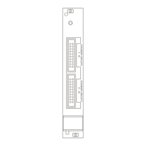
- Page 38 BVR20 Microdrive General Description The Baldwin Boxall Ambient Noise System is based around the BVR20 Microdrive. BVRAMB ambient noise sensors are connected to the BVR20 via BVRCI interface cards. The BVRCI cards connect via ribbon cable assemblies to BVRIO40 cards located in the BVR20.
- Page 39 BVRAMB Ambient Noise Sensors Care should be taken in the positioning of the BVRAMB ambient noise sensors, they need to be as close to the ambient noise source as possible, and as far away from the loudspeakers as possible. Do not position them in the dispersion angle of the loudspeakers, or close to a permanent noise source (air conditioning, fruit machines etc) In high ceiling rooms position the sensor so that it closer to the floor than the ceiling Cables should be 3-core fire rated, with a conductor cross sectional area of 1.0mm or...
- Page 40 Setting Up The Ambient Noise Sensing function is controlled either from the BVR20 front panel, or a Laptop Computer if the Configuration software is fitted. The following identifies the BVR20 LCD screens, and assumes that the user has access authority. With the System Configuration Keyswitch in the ON position, press the PAGE DOWN key, the first page will identify the software version of the BVR20.
- Page 41 The right hand of the screen displays the two ambient noise sections. ANS displays the returned signal from the sensor; this is a dynamic figure and will vary between -00 and -12 with the ambient noise. The figure –00 represents no attenuation, whereas –12 represents the maximum (20dB) of attenuation.
- Page 42 Software Versions BVR8-30. Released 25-10-2001 Faster response time from ANS sensors. BVR8-43. Released 21-07-2003 Under high reverberation conditions it is possible that the level increase inhibit detector is not effective and the echo is sensed as ambient noise during pauses in the broadcast message. This run away is made more apparent if the sensor sensitivity is set too high and in a tunnel environment.
Need help?
Do you have a question about the VIGIL BVR20 and is the answer not in the manual?
Questions and answers